ENGINE ASSEMBLY REMOVAL

-
PLACE FRONT WHEELS FACING STRAIGHT AHEAD
-
DISCONNECT CABLE FROM NEGATIVE BATTERY TERMINAL
-
DRAIN ENGINE COOLANT
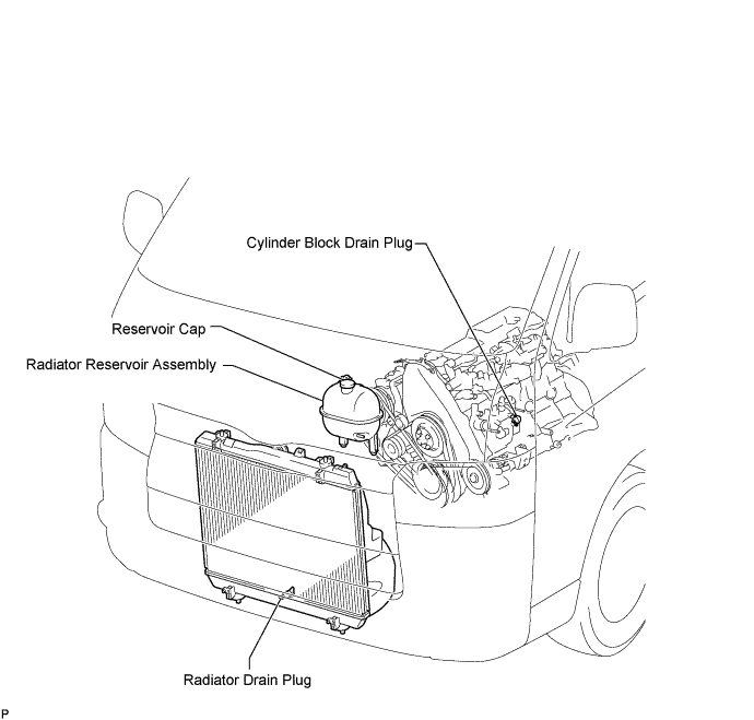
CAUTION:
To avoid the danger of being burned, do not remove the reservoir cap while the engine and radiator assembly are still hot. Thermal expansion will cause hot engine coolant and steam to blow out from the radiator assembly.
-
Loosen the radiator drain plug.
-
Remove the reservoir cap.
-
Loosen the cylinder block drain plug and drain the coolant.
-
Tighten the radiator drain plug.
-
Tighten the cylinder block drain plug.
- Torque:
- 13 N*m { 130 kgf*cm, 9 ft.*lbf }
-
-
DRAIN ENGINE OIL
Note
-
Prolonged and repeated contact with mineral oil will result in the removal of natural fats from the skin, leading to dryness, irritation and dermatitis. In addition, used engine oil contains potentially harmful contaminants which may cause skin cancer.
-
Exercise caution in order to minimize the duration and frequency of skin contact with used oil. Wear protective clothing and gloves. Wash your skin thoroughly with soap and water, or use water-less hand cleaner to remove any used engine oil. Do not use gasoline, thinners, or solvents.
-
In order to preserve the environment, used oil and the used oil filter must be disposed of only at designated disposal sites.
-
Remove the oil filler cap.
-
Remove the oil drain plug, and drain the oil into a container.
-
Clean the drain plug, and install it with a new gasket.
- Torque:
- 35 N*m { 350 kgf*cm, 25 ft.*lbf }
-
-
REMOVE FRONT SEAT ASSEMBLY RH (for Hi-back Seat Type)
Tech Tips
Use the same procedures described for the LH side. Click here
-
REMOVE FRONT SEAT ASSEMBLY RH (for Low-back Seat Type)
Tech Tips
Use the same procedures described for the LH side. Click here
-
REMOVE FRONT DOOR SCUFF PLATE RH
-
REMOVE ENGINE SERVICE HOLE SUB COVER SUB-ASSEMBLY
-
Turn back the carpet, and remove the engine service hole cover sub-assembly.
-
-
REMOVE VANE PUMP V BELT
-
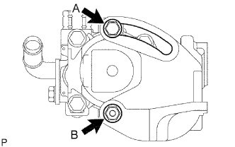
Loosen the bolt A and nut B, and remove the V belt.
-
-
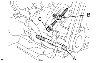
REMOVE V (COOLER COMPRESSOR TO CRANKSHAFT PULLEY) BELT NO.1 (W/ AIR CONDITIONING)
-
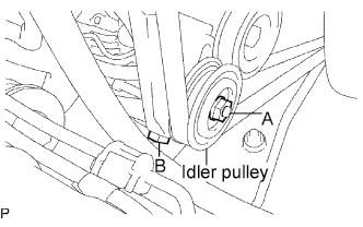
Loosen the nut A and bolt B, and remove the V belt.
-
-
REMOVE FAN & GENERATOR V BELT (w/o Air Conditioning)
-
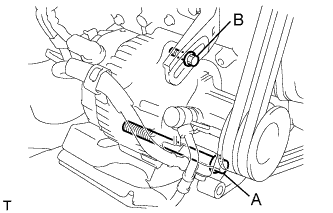
Loosen the bolts A and B, and remove the V belt.
-
-
REMOVE FAN & GENERATOR V BELT (w/ Air Conditioning)
-
Loosen the bolts A and B.
-
Loosen the adjusting bolt C, and remove the V belt.
-
-
DISCONNECT RADIATOR HOSE INLET
-
DISCONNECT RADIATOR HOSE NO.4
-
DISCONNECT INJECTION PUMP TO FUEL FILTER FUEL HOSE OR PIPE
-
SEPARATE AIR CLEANER HOSE NO.2
-
Loosen the bolt, and disconnect the air cleaner hose No.2.
-
-
REMOVE COMPRESSOR AND MAGNETIC CLUTCH
-
SEPARATE VANE PUMP OIL RESERVOIR ASSEMBLY
-
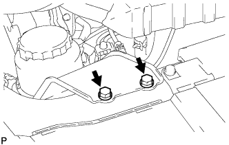
Remove the 2 bolts and vane pump oil reservoir assembly.
Note
Suspend the vane pump oil reservoir assembly with wire to prevent power steering fluid from spilling out.
-
-
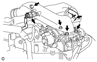
DISCONNECT ENGINE WIRE
-
Disconnect the ECM connector Click here.
-
Disconnect the clamp and ground cable of the engine wire.
-
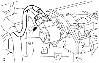
Remove the nut then remove the starter wire harness.
-
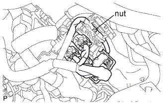
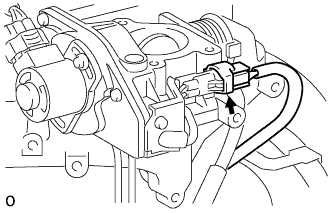
Remove the connector and nut, as shown the illustration.
-
-
REMOVE EXHAUST PIPE SUB-ASSEMBLY FRONT NO.2 (for Long Wheelbase)
-
Remove the 4 bolts, 2 compression springs.
-
Disconnect the exhaust pipe support, and remove the exhaust pipe assembly front No.2 and 2 gaskets.
-
-
REMOVE EXHAUST PIPE SUB-ASSEMBLY FRONT NO.2 (for Super Long Wheelbase)
-
Remove the 4 bolts, 2 nuts, 2 compression springs.
-
Disconnect the exhaust pipe support, and remove the exhaust pipe assembly front No.2 and 2 gaskets.
-
-
REMOVE EXHAUST PIPE SUB-ASSEMBLY FRONT NO.1 (for Long Wheelbase)
-
Loosen the clamp bolt, and separate the exhaust pipe support bracket No.1 from the exhaust pipe sub-assembly front No.1.
-
Remove the 3 bolts, exhaust pipe sub-assembly front No.1 and gasket from the exhaust manifold.
-
-
REMOVE EXHAUST PIPE SUB-ASSEMBLY FRONT NO.1 (for Super Long Wheelbase)
-
Loosen the clamp bolt, and separate the exhaust pipe support bracket No.1 from the exhaust pipe sub-assembly front No.1.
-
Remove the 3 bolts, exhaust pipe sub-assembly front No.1 and gasket from the exhaust manifold.
-
-
REMOVE PROPELLER SHAFT ASSEMBLY (for Long Wheelbase)
-
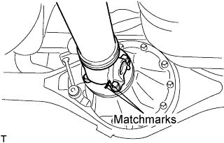
Put matchmarks on both flanges.
-
Remove the 4 nuts, bolts and washers.
Tech Tips
If the flange connection is hard to separate, temporarily tighten one nut only and evenly tap the flange with a brass bar and hammer to separate the propeller shaft assembly from the differential companion flange.
-
Remove the propeller shaft assembly.
-
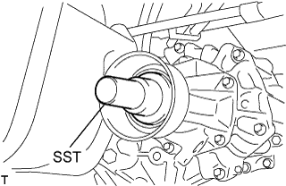
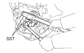
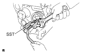
Insert SST in the transmission to prevent oil leakage.
Note
Do not damage the oil seal.
-
Use the following SST for the automatic transmission
- SST
- 09325-40010
-
Use the following SST for the manual transmission
- SST
- 09325-20010
-
-
-
REMOVE PROPELLER SHAFT ASSEMBLY (for Super Long Wheelbase)
-
Put matchmarks on both flanges.
-
Remove the 4 nuts, bolts and washers.
Tech Tips
If the flange connection is hard to separate, temporarily tighten one nut only and evenly tap the flange with a brass bar and hammer to separate the propeller with center bearing shaft assembly from the differential companion flange.
-
Remove the 2 bolts and center support bearing assembly No.1.
-
Remove the propeller with center bearing shaft assembly.
-
Insert SST in the transmission to prevent oil leakage.
Note
Do not damage the oil seal.
-
Use the following SST for the automatic transmission.
- SST
- 09325-40010
-
Use the following SST for the manual transmission.
- SST
- 09325-20010
-
-
-
SEPARATE SPEED SENSOR FRONT LH (w/ ABS)
-
Remove the 2 bolts, and separate the speed sensor from the steering knuckle.
Note
-
Be careful not to damage the speed sensor.
-
Prevent foreign matter from adhering to the speed sensor.
-
-
-
SEPARATE SPEED SENSOR FRONT RH (w/ ABS)
Tech Tips
Use the same procedures described for the LH side.
-
SEPARATE FRONT DISC BRAKE CALIPER ASSEMBLY LH
-
Remove the 2 bolts, and disconnect the brake caliper assembly.
Note
Use a wire or an equivalent to keep the brake caliper from hanging down by the flexible hose.
-
-
SEPARATE FRONT DISC BRAKE CALIPER ASSEMBLY RH
Tech Tips
Use the same procedures described for the LH side.
-
SEPARATE FRONT SUSPENSION ARM SUB-ASSEMBLY UPPER LH
-
Remove the cotter pin and loosen the nut.
- SST
- 09628-62011
Note
Do not remove the nut.
-
Using SST, separate the steering knuckle from the suspension upper arm and remove the nut.
Note
-
Fix the steering knuckle with a wire so that the flexible hose does not receive excessive force.
-
Do not damage the ball joint dust cover.
-
-
-
SEPARATE FRONT SUSPENSION ARM SUB-ASSEMBLY UPPER RH
Tech Tips
Use the same procedures described for the LH side.
-
SEPARATE SHOCK ABSORBER ASSEMBLY FRONT LH
-
Remove the bolt and separate the front shock absorber from the front suspension lower arm.
-
-
SEPARATE SHOCK ABSORBER ASSEMBLY FRONT RH
Tech Tips
Use the same procedures described for the LH side.
-
SEPARATE TRANSMISSION CONTROL CABLE ASSEMBLY
-
Put matchmarks on the control cable assembly and the outer lever.
-
Remove the 2 nuts and separate the transmission control cable from the outer lever.
-

Using a screwdriver, disengage the claws of the 2 clips.
-
Remove the transmission control cable and 2 clips from the transmission control cable bracket No.1.
-
-
DISCONNECT WIRE HARNESS
-
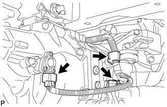
Disconnect the 2 connectors and clamp.
-
-
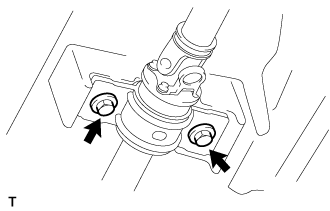
SEPARATE CLUTCH RELEASE CYLINDER ASSEMBLY
-
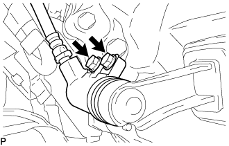
Remove the 2 bolts and separate the clutch release cylinder.
-
-
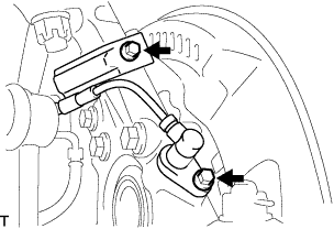
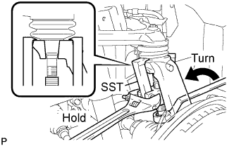
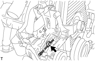
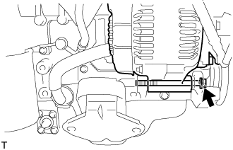
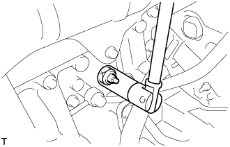
SEPARATE STEERING TORQUE SHAFT ASSEMBLY
-
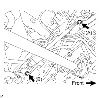
Loosen bolt (A) and remove bolt (B), then slide the steering torque shaft assembly.
Tech Tips
-
Do not remove bolt (A).
-
Do not disconnect the steering torque shaft assembly from the power steering link assembly.
-
-
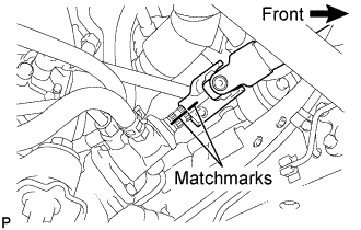
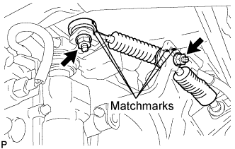
Put matchmarks on the steering torque shaft assembly and the power steering link assembly.
-
Separate the steering torque shaft assembly from the power steering link assembly.
-
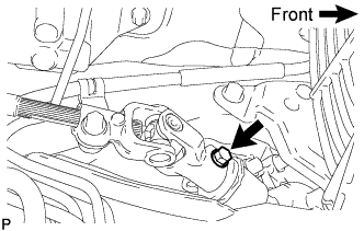
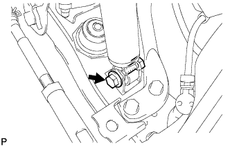
Remove the bolt and slide the steering torque shaft assembly.
-
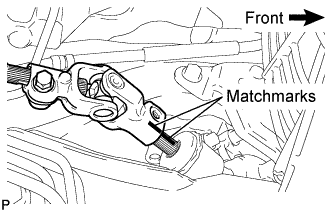
Put matchmarks on the steering torque shaft assembly and the steering bevel gear assembly.
-
Remove the steering torque shaft assembly from the steering bevel gear assembly.
-
-
REMOVE ENGINE W/ TRANSMISSION ASSEMBLY
-
Using the engine lifter, hold the engine assembly and separate the rear engine mounting.
-
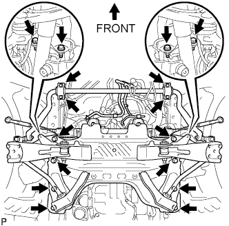
Remove the stabilizer bracket and 16 bolts of the front suspension cross member.
-
Remove the engine assembly w/ transmission to the vehicle.
-
-
REMOVE STARTER ASSEMBLY (for 2.2 kW Type)
-
Disconnect the starter connector.
-
Remove the terminal cap.
-
Remove the nut, and disconnect the 30 terminal.
-
Remove the nut, 2 bolts, and stay.
-
Remove the nut 2 bolts, and starter assembly.
-
-
REMOVE STARTER ASSEMBLY (for 2.7 kW Type)
-
Disconnect the starter connector.
-
Remove the terminal cap.
-
Remove the nut, and disconnect the 30 terminal.
-
Remove the nut and, 2 bolts, stay and starter assembly.
-
-
REMOVE MANUAL TRANSMISSION UNIT ASSEMBLY
-
REMOVE CLUTCH COVER ASSEMBLY
-
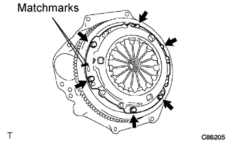
Put matchmarks on the clutch cover assembly and the flywheel sub-assembly.
-
Loosen each set bolt one turn at a time until spring tension is released.
Note
Do not drop the clutch disc assembly.
-
Remove the set bolts, and pull off the clutch cover assembly.
-
-
REMOVE CLUTCH DISC ASSEMBLY
Note
Keep the lining part of the clutch disc assembly, the pressure plate and surface of the flywheel sub-assembly away from oil and foreign matter.
-
REMOVE FLYWHEEL SUB-ASSEMBLY
-
Fix the crankshaft with SST, then remove the 8 bolts and flywheel.
- SST
- 09213-54015 ( 91651-60855 )
- 09330-00021
-
-
REMOVE REAR END PLATE
-
Remove the 2 bolts and rear end plate.
-
-
REMOVE ENGINE WIRE
-
Remove the engine wire to the engine assembly.
-
-
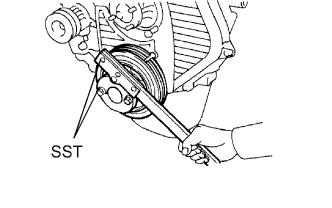
SEPARATE VANE PUMP ASSEMBLY
-
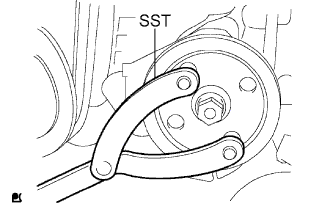
Using SST, stop the pulley rotation and loosen the nut.
- SST
- 09960-10010 ( 09962-01000, 09963-01000 )
-
Remove the nut and vane pump pulley from the vane pump shaft.
-
Remove the 2 bolts and nut, and separate the vane pump assembly.
Tech Tips
Separate the vane pump with the hoses connected, and it should be hung with a rope.
-
-
INSTALL ENGINE HANGER NO.2
-
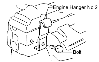
Install the engine hanger No.2 in the correct direction.
- Torque:
- 37 N*m { 380 kgf*cm, 27 ft.*lbf }
Part No.: Engine hanger No.2 12282-54060 Bolt 91622-61022
-
-
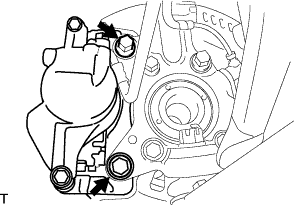
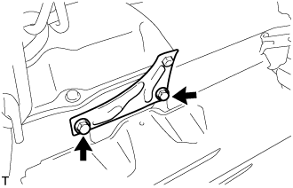
SEPARATE ENGINE MOUNTING INSULATOR FRONT
-
Remove the 4 bolts, and separate the engine mounting insulator front.
-
-
REMOVE FAN BELT ADJUSTING BAR (w/o Air Conditioning)
-
Remove the 3 bolts and fan belt adjusting bar.
-
-
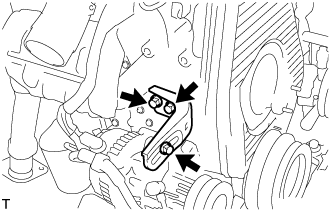
REMOVE COMPRESSOR MOUNTING BRACKET (w/ Air Conditioning)
-
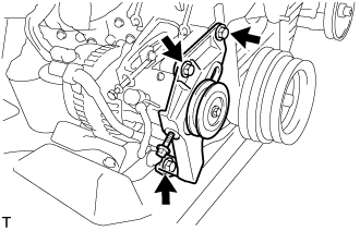
Remove the 3 bolts and compressor mounting bracket.
-
Remove the bolt and spacer.
-
Remove the 4 bolts and compressor mounting bracket.
-
-
REMOVE TIMING BELT
-
REMOVE INTAKE AIR CONNECTOR SUB-ASSEMBLY
-
Disconnect the ventilation hose.
-
Disconnect the turbo pressure sensor connector.
-
Remove the bolt, 3 nuts, intake air connector and gasket.
-
-
REMOVE INTAKE AIR CONNECTOR BRACKET
-
Remove the 2 bolts and intake air connector bracket.
-
-
REMOVE VENTURI ASSEMBLY
-
Disconnect the throttle open switch connector.
-
Disconnect the throttle control motor connector.
-
Remove the venturi and gasket.
-
-
REMOVE INJECTION PIPE SET
-
Loosen the 8 union nuts of the 4 injection pipes.
-
Remove the 2 nuts, 2 upper pipe clamps, and 4 injection pipes with lower pipe clamps.
-
-
REMOVE GLOW PLUG NO.1 CONNECTOR
-
Remove the vehicle's side wire harness, glow plug screw grommets and nuts, and disconnect the glow plug No.1 connector.
-
-
REMOVE NOZZLE LEAKAGE PIPE ASSEMBLY
-
Disconnect the fuel hose from the leakage pipe.
-
Remove the 4 nuts, leakage pipe and the 4 ring packing washers.
-
-
REMOVE NOZZLE HOLDER & NOZZLE SET
-
Using SST, remove the 4 injection nozzles, 4 injection nozzle seats and 4 injection nozzle seat gaskets.
- SST
- 09268-64010 ( 09268-64020 )
-
-
REMOVE GLOW PLUG ASSEMBLY
-
Using a 12 mm deep socket wrench, remove the 4 glow plugs.
-
-
REMOVE INJECTION PUMP DRIVE PULLEY
-
Using SST, remove the pulley nut.
- SST
- 09213-14010 ( 91651-60865 )
- 09330-00021
-
Using SST, remove the drive pulley.
- SST
- 09950-50013 ( 09951-05010, 09952-05010, 09953-05010, 09954-05021 )
-
-
REMOVE INJECTION OR SUPPLY PUMP ASSEMBLY
-
Disconnect the engine speed sensor connector.
-
Disconnect the spill control valve connector.
-
Disconnect the correction unit connector.
-
Disconnect the timer control valve connector.
-
Disconnect the fuel temperature sensor connector.
-
Disconnect the engine wire clamp.
-
Disconnect the 3 fuel hoses.
-
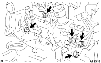
Disconnect the 3 bolts and injection pump stay No.1.
-
Remove the 2 nuts and injection or supply pump assembly.
-
-
REMOVE CRANK POSITION SENSOR
-
Disconnect the crank position sensor connector.
-
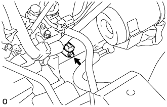
Remove the bolt and crank position sensor.
-
-
REMOVE WATER OUTLET HOUSING
-
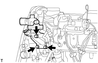
Remove the 3 bolts, water outlet, outlet housing assembly and gasket.
-
-
REMOVE INTAKE MANIFOLD
-
Remove the 6 bolts, 2 nuts, intake manifold and gasket.
-
-
REMOVE WATER BY-PASS HOSE UNION
-
Remove the water by-pass hose union.
-
-
REMOVE CYLINDER BLOCK WATER DRAIN COCK SUB-ASSEMBLY
-
Remove the cylinder block water drain cock sub-assembly.
-
-
REMOVE ENGINE OIL LEVEL SENSOR
-
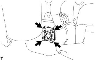
Remove the 4 bolts and engine oil level sensor.
-
-
REMOVE EXHAUST PIPE SUPPORT BRACKET NO.1
-
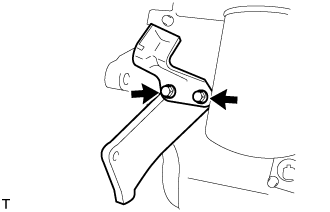
Remove the 2 bolts, exhaust pipe support bracket No.1 and stiffener plate RH.
-
-
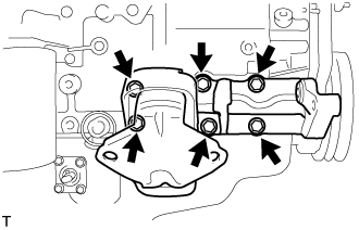
REMOVE PUMP BRACKET
-
Remove the 6 bolts and pump bracket.
-
-
REMOVE GENERATOR W/ VACUUM PUMP ASSEMBLY
-
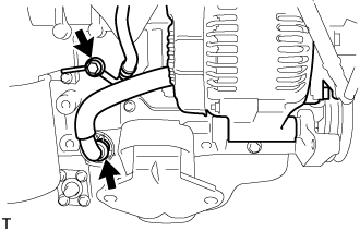
Remove the bolt and disconnect the hose.
-
Remove the clip and disconnect the hose.
-
Remove the bolt and generator w/ vacuum pump assembly.
-
-
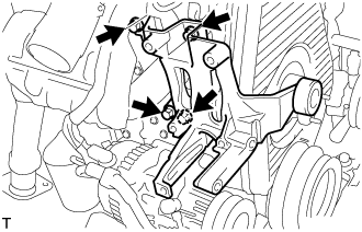
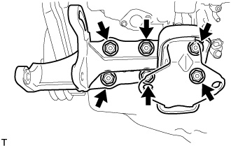
REMOVE ENGINE MOUNTING BRACKET FRONT NO.1 RH
-
Remove the 6 bolts and engine mounting bracket front No.1 RH.
-
-
REMOVE OIL LEVEL GAGE SUB-ASSEMBLY
-
REMOVE OIL LEVEL GAGE GUIDE
-
Remove the oil level gage guide.
-
-
REMOVE EXHAUST MANIFOLD HEAT INSULATOR NO.1
-
Remove the 3 bolts and exhaust manifold heat insulator No.1.
-
-
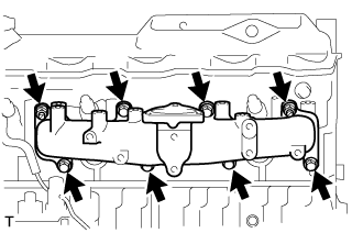
REMOVE EXHAUST MANIFOLD
-
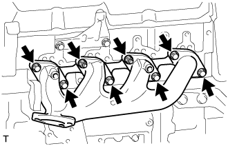
Remove the 6 bolts, 2 nuts and exhaust manifold.
-
Remove the exhaust manifold gasket from the cylinder head.
-
-
REMOVE OIL FILTER SUB-ASSEMBLY
-
Using SST, remove the oil filter.
- SST
- 09228-44011
-
-
REMOVE OIL FILTER BRACKET SUB-ASSEMBLY
-
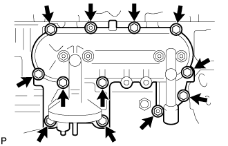
Remove the 10 bolts, 2 nuts, oil filter bracket, and gasket.
-
-
REMOVE ENGINE OIL PRESSURE SWITCH ASSEMBLY
-
Using a 24 mm deep socket wrench, remove the oil pressure switch.
-
-
REMOVE WIRE HARNESS CLAMP BRACKET
-
Remove the bolt and wire harness clamp bracket.
-