БЕССТУПЕНЧАТАЯ ТРАНСМИССИЯ В СБОРЕ СНЯТИЕ

CAUTION / NOTICE / HINT
The necessary procedures (adjustment, calibration, initialization, or registration) that must be performed after parts are removed, installed, or replaced during the continuously variable transaxle assembly removal/installation are shown below.
| Replacement Part or Procedure | Necessary Procedures | Effects/Inoperative when not Performed | Link |
|---|---|---|---|
| Battery terminal is disconnected/reconnected | Drive the vehicle until stop and start control is permitted (approximately 5 to 60 minutes) | Stop and start system | |
| Memorize steering angle neutral point | Panoramic view monitor system | ||
| Initialize back door lock | Power door lock control system | ||
| Initialize servo motor | Air conditioning system | ||
| Reset slide door close position | Power slide door system | ||
| Reset back door close position | Power back door system | ||
| Replacement of ECM | Perform Vehicle Identification Number (VIN) or frame number registration | DTC is stored | |
| ECU Communication ID Registration (Immobiliser system) | Engine start function | See Service Bulletin for the registration method. | |
| Perform code registration (Immobiliser system) |
|
See Service Bulletin for the registration method. | |
| Perform the following procedures in the order shown:
|
|
||
| Replacement of continuously variable transaxle assembly | Perform the following procedures in the order shown:
|
|
|
| CVT fluid | ATF thermal degradation estimate reset | The value of the Data List item "ATF Thermal Degradation Estimate" is not estimated correctly | |
|
Inspection After Repair |
|
|
| Replacement of starter assembly Note When the starter assembly is replaced, "ST NO. 1 relay" and "ST NO. 2 relay" must be also replaced. |
Clear Number of Starter Operations | Stop and start system | |
|
Bleed the oil pump assembly with motor (continuously variable transaxle assembly) | ||
| Front wheel alignment adjustment |
|
|
|
| Work that changes the vehicle height such as replacement or removal/installation of the rear height control sensor sub-assembly LH or replacement of suspension components | Initialize headlight light control ECU sub-assembly LH | Headlight leveling function | |
| Removal/installtaion of the radiator grille | Television camera view adjustment | Panoramic view monitor system | |
| Replacement of battery | Switch battery type | Stop and Start System |
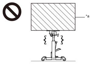
CAUTION:
The engine assembly with continuously variable transaxle assembly is very heavy. Be sure to follow the procedure described in the repair manual, or the engine lifter may suddenly drop.
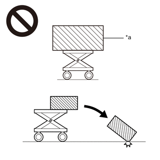
| *a | An Object Exceeding Weight Limit of Engine Lifter |
PROCEDURE
-
REMOVE FLYWHEEL HOUSING UNDER COVER
-
REMOVE DRIVE PLATE AND TORQUE CONVERTER ASSEMBLY SETTING BOLT
-
Turn the crankshaft to gain access to the 6 drive plate and torque converter assembly setting bolts and remove each drive plate and torque converter assembly setting bolt while holding the crankshaft pulley bolt with a wrench.
Tech Tips
There will be one black colored drive plate and torque converter assembly setting bolt.
-
-
REMOVE FRONT SUSPENSION MEMBER BRACE SUB-ASSEMBLY LH
-
REMOVE FRONT SUSPENSION MEMBER BRACE SUB-ASSEMBLY RH
Tech Tips
Use the same procedure as for the LH side.
-
REMOVE FRONT SUSPENSION CROSSMEMBER SUB-ASSEMBLY
-
REMOVE ENGINE ASSEMBLY WITH TRANSAXLE
-
INSTALL ENGINE HANGER
-
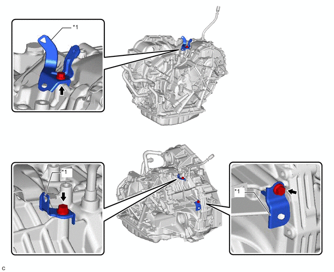
REMOVE FRONT ENGINE MOUNTING INSULATOR
-
REMOVE FRONT ENGINE MOUNTING BRACKET
-
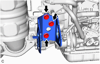
Remove the 3 bolts and front engine mounting bracket from the transaxle housing sub-assembly.
-
-
REMOVE REAR ENGINE MOUNTING INSULATOR
-
REMOVE REAR ENGINE MOUNTING BRACKET
-
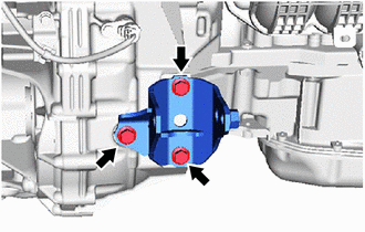
Remove the 3 bolts and rear engine mounting bracket from the transaxle housing sub-assembly.
-
-
REMOVE ENGINE MOUNTING BRACKET LH
-
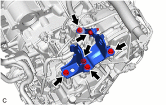
Remove the 6 bolts and engine mounting bracket LH and engine mounting stay LH from the transaxle case.
-
-
REMOVE OIL COOLER
-
DISCONNECT ENGINE WIRE
-
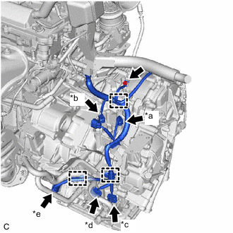
*a Transmission Revolution Sensor (NIN) Connector *b Transmission Revolution Sensor (NT) Connector *c Transmission Wire Connector *d Park/Neutral Position Switch Assembly Connector *e Oil Pump with Motor Assembly Connector Disconnect the transmission revolution sensor (NIN) connector.
-
Disconnect the transmission revolution sensor (NT) connector.
-
Disconnect the transmission wire connector.
-
Disconnect the park/neutral position switch assembly connector.
-
Disconnect the oil pump with motor assembly connector.
-
Remove the bolt.
-
Disengage the 3 clamps and disconnect the engine wire.
-
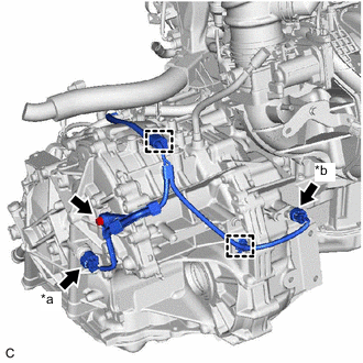
*a Oil Pressure Sensor Connector *b Transmission Revolution Sensor (NOUT) Connector Disconnect the oil pressure sensor connector.
-
Disconnect the transmission revolution sensor (NOUT) connector.
-
Disengage the 2 clamps.
-
Remove the bolt.
-
-
REMOVE AUTOMATIC TRANSMISSION CASE COVER
-
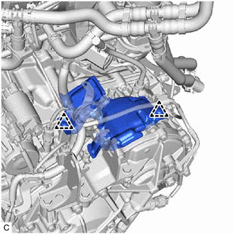
Remove the 2 clips and automatic transmission case cover from the transaxle case.
-
-
REMOVE CONTINUOUSLY VARIABLE TRANSAXLE ASSEMBLY
CAUTION:
The continuously variable transaxle assembly is very heavy. Be sure to follow the procedure described in the repair manual, or the transmission jack may suddenly drop or a part may fall.
*a Object Exceeding Weight Limit of Transmission Jack
-
Using a transmission jack attachment, set the continuously variable transaxle assembly on a transmission jack.
Note
-
Secure the continuously variable transaxle assembly to the transmission jack using a suitable adapter, such as a rope or attachment.
-
To prevent the transaxle oil (CVT) pan sub-assembly from deforming, do not place any attachments under the transaxle oil (CVT) pan sub-assembly.
-
Hold the engine assembly with a suitable adapter, such as a rope, during the operation.
-
-
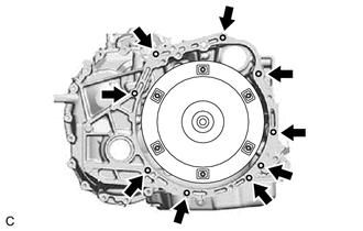
Remove the 9 bolts and continuously variable transaxle assembly from the engine assembly.
Note
To prevent damage to the 2 knock pins, do not pry between the continuously variable transaxle assembly and engine assembly.
-
-
REMOVE TORQUE CONVERTER ASSEMBLY
-
Remove the torque converter assembly from the continuously variable transaxle assembly.
Note
Remove the torque converter assembly from the input shaft horizontally.
-
-
REMOVE CVT OIL PUMP TYPE T OIL SEAL
CAUTION:
-
Do not remove the front oil pump assembly from the continuously variable transaxle assembly main body, as there is a possibility of the entry of dust and foreign matter.
-
Clean the work area, the tools to be used, and other equipment, etc. thoroughly before the operation, as there is the possibility that a continuously variable transaxle assembly malfunction, which may prevent the vehicle from being driven, may occur if dust or fine foreign matter enters the continuously variable transaxle assembly.
-
Do not use cotton work gloves, cloths, paper towels, etc. that may produce lint, dust or foreign matter.
-
Perform the operation as quickly as possible, as dust and foreign matter may enter the continuously variable transaxle assembly while the torque converter assembly is not attached to it.
-
Do not use an air gun until the torque converter assembly has been installed, as it may cause dust and foreign matter to be stirred up.
-
Clean the tips of both the claws of SST and the center bolt.
- SST
- 09308-10010
-
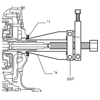
*1 CVT Type T Oil Seal *a Claw Using SST, remove the CVT oil pump type T oil seal from the continuously variable transaxle assembly.
Note
Pay attention to the angle of the claws of SST when opening them, and ensure that they do not come into contact with the oil pump housing, as there is the possibility that metal particles may be produced if they do.
-
-
REMOVE WIRE HARNESS CLAMP BRACKET
-
Remove the 3 bolts and 3 wire harness clamp brackets from the transaxle case.
*1 Wire Harness Clamp Bracket - -
-
-
REMOVE NO. 1 TRANSMISSION CONTROL CABLE BRACKET
-
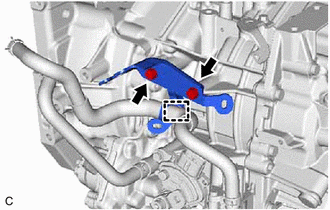
Disengage the outlet No. 1 oil cooler hose clamp.
-
Remove the 2 bolts and No. 1 transmission control cable bracket from the transaxle case.
-
-
REMOVE TUBE CONNECTOR
-
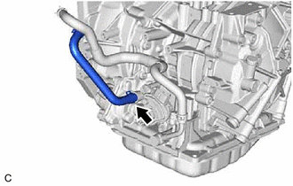
Slide the clip and disconnect the inlet No. 1 oil cooler hose from the tube connector.
Note
Do not damage the coating of the inlet No. 1 oil cooler hose insertion part of the tube connector.
-
Remove the tube connector from the transaxle case.
-
Remove the O-ring from the tube connector.
-
-
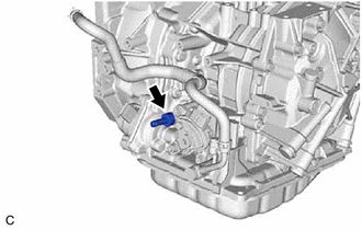
REMOVE OIL COOLER ELBOW SUB-ASSEMBLY
-
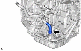
Slide the clip and disconnect the outlet No. 1 oil cooler hose from the oil cooler elbow sub-assembly.
Note
Do not damage the coating of the outlet No. 1 oil cooler hose insertion part of the oil cooler elbow sub-assembly.
-
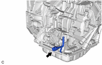
Remove the union bolt, oil cooler elbow sub-assembly and gasket from the transaxle case.
-
-
REMOVE WITH HEAD STRAIGHT SCREW PLUG
Tech Tips
Perform this procedure only when replacement of the with head straight screw plug is necessary.
-
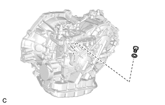
Remove the with head straight screw plug and gasket from the transaxle case.
-
-
REMOVE BREATHER PLUG HOSE
Tech Tips
Perform this procedure only when replacement of the breather plug hose is necessary.
-
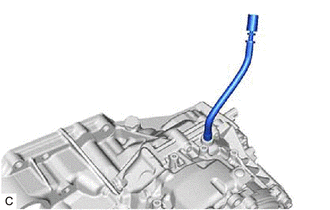
Remove the breather plug hose from the transaxle housing sub-assembly.
-
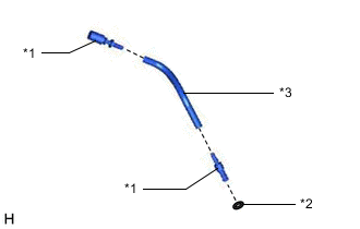
*1 Breather Plug *2 O-ring *3 Breather Plug Hose Remove the 2 breather plugs from the breather plug hose.
-
Remove the O-ring from the breather plug.
-
-
INSPECT TORQUE CONVERTER ASSEMBLY
-
INSPECT DRIVE PLATE AND RING GEAR SUB-ASSEMBLY