SEAT HEATER SYSTEM Seat Heater Switch Circuit
DESCRIPTION
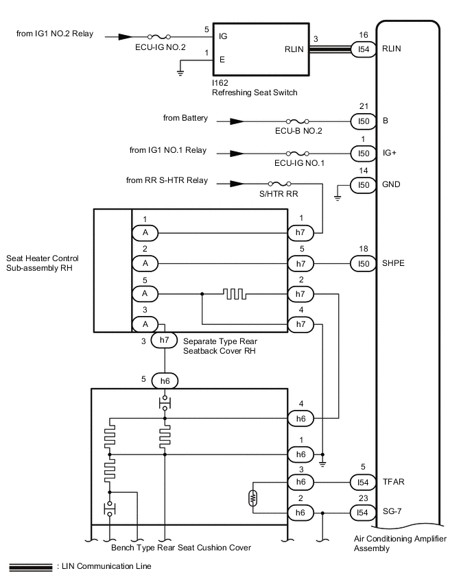
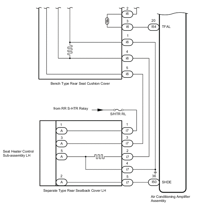
When the refreshing seat switch is operated, the air conditioning amplifier assembly receives the signal via the LIN communication line, and operates the seat heater for the corresponding rear seat.
WIRING DIAGRAM
CAUTION / NOTICE / HINT
Note
-
If the battery voltage is low, the seat heater system may not operate. When "High Power Consumption / Partial Limit On AC/Heater Operation" is displayed on the multi-information display in the combination meter assembly, inspect the battery, referring to On-vehicle Inspection for the charging system.
Tech Tips
If the battery voltage is low, "Operation Limitation Control History Count (Level 1)" and "Operation Limitation Control History Count (Level 2) is counted.
-
for 8AR-FTS: Click here
-
for 3ZR-FAE: Click here
-
If the battery voltage is low, the seat heater system may not operate. Refer to Data List for the power steering system.
-
for Manual Tilt and Manual Telescopic Steering Column: Click here
-
for Power Tilt and Power Telescopic Steering Column: Click here
-
When the battery is disconnected or the air conditioning amplifier assembly is replaced, be sure to perform servo motor initialization.
PROCEDURE
-
CHECK HARNESS AND CONNECTOR (REFRESHING SEAT SWITCH - BATTERY AND BODY GROUND)
-
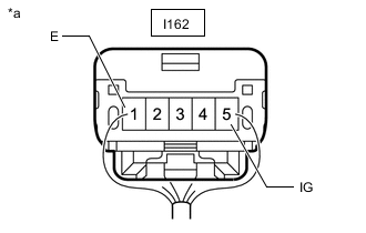
*a Rear view of wire harenss connector
(to Refreshing Seat Switch Connector)
Disconnect the refreshing seat switch connector.
-
Measure the resistance according to the value(s) in the table below.
Standard Resistance Tester Connection Condition Specified Condition I162-1 (E) - Body ground Always Below 1 Ω -
Measure the voltage according to the value(s) in the table below.
Standard Voltage Tester Connection Switch Condition Specified Condition 162-5 (IG) - Body ground Engine switch off Below 1 V 162-5 (IG) - Body ground Engine switch on (IG) 11 to 14 V Result Proceed to OK NG
NG 
REPAIR OR REPLACE HARNESS OR CONNECTOR
OK 
-
-
CHECK HARNESS AND CONNECTOR (REFRESHING SEAT SWITCH - AIR CONDITIONING AMPLIFIER ASSEMBLY)
-
Disconnect the I162 refreshing seat switch connector.
-
Disconnect the I54 air conditioning amplifier assembly connector.
-
Measure the resistance according to the value(s) in the table below.
Standard Resistance Tester Connection Condition Specified Condition I162-3 (RLIN) - I54-16 (RLIN) Always Below 1 Ω I162-3 (RLIN) or I54-16 (RLIN) - Body ground Always 10 k Ω or higher Result Proceed to OK NG
NG
REPAIR OR REPLACE HARNESS OR CONNECTOR
OK
-
-
CHECK AIR CONDITIONING AMPLIFIER ASSEMBLY (OUTPUT SIGNAL)
-
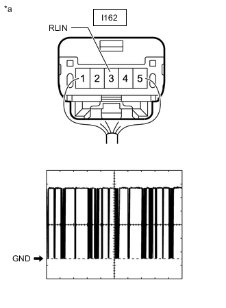
*a Component with harness connected
(Refreshing Seat Switch)
Using an oscilloscope, check the waveform.
Item Content Tester Connection I162-3 (RLIN) - Body ground Tool Setting 2 V/DIV.,20 ms./DIV. Condition Engine switch on (IG) OK The waveform displays properly. Result Proceed to OK NG
NG
REPLACE AIR CONDITIONING AMPLIFIER ASSEMBLY Click here
OK
-
-
CHECK REFRESHING SEAT SWITCH (OUTPUT SIGNAL)
-
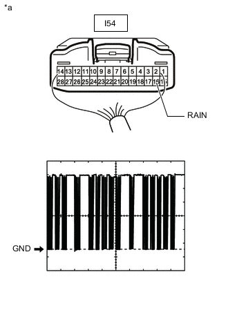
*a Component with harness connected
(Air Conditioning Amplifier Assembly)
Using an oscilloscope, check the waveform.
Item Content Tester Connection I54-16 (RLIN) - Body ground Tool Setting 2 V/DIV.,20 ms./DIV. Condition Engine switch on (IG) OK The waveform displays properly. Result Proceed to OK NG
NG
REPLACE REFRESHING SEAT SWITCH Click here
OK
-
-
INSPECT REFRESHING SEAT SWITCH
-
Remove the refreshing seat switch.
-
Inspect the refreshing seat switch.
Result Proceed to OK NG
OK
REPLACE AIR CONDITIONING AMPLIFIER ASSEMBLY Click here
NG
REPLACE REFRESHING SEAT SWITCH Click here
-