THEFT DETERRENT SYSTEM Ignition Switch Circuit
| DTC Code | DTC Name |
|---|---|
| Ignition Switch Circuit |
DESCRIPTION
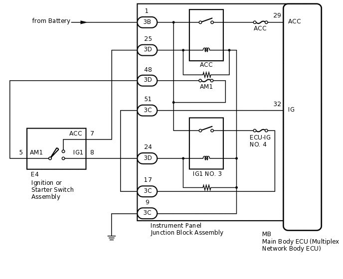
The main body ECU (multiplex network body ECU) determines the ignition switch position (LOCK, ACC, ON) based on signals from the IG or ACC circuit.
WIRING DIAGRAM
CAUTION / NOTICE / HINT
Inspect the fuses for circuits related to this system before performing the following procedure.
PROCEDURE
READ VALUE USING GTS (ACC SW, IG SW)
Connect the GTS to the DLC3.
Turn the ignition switch to ON.
Turn the GTS on.
Enter the following menus: Body Electrical / Main Body / Data List.
According to the display on the GTS, read the Data List.
Body Electrical > Main Body > Data List
Tester Display
Measurement Item
Range
Normal Condition
Diagnostic Note
ACC SW
Ignition switch
ON or OFF
ON: Ignition switch ACC
OFF: Ignition switch LOCK
-
IG SW
Ignition switch
ON or OFF
ON: Ignition switch ON
OFF: Ignition switch LOCK or ACC
-
Body Electrical > Main Body > Data List
Tester Display
ACC SW
IG SW
OK
ON or OFF appears on the screen according to whether the ignition switch is in ON or is in LOCK or ACC.
Result
Proceed to
OK
NG
INSPECT IGNITION OR STARTER SWITCH ASSEMBLY
-
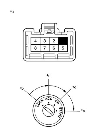
*a
Component without harness connected
(Ignition or Starter Switch Assembly)
*b
LOCK
*c
ACC
*d
ON
*e
START
Remove the ignition or starter switch assembly.
for 1ZR-FAE:Click here
for 8NR-FTS:Click here
Measure the resistance according to the value(s) in the table below.
Standard Resistance
Tester Connection
Condition
Specified Condition
5 - 7
Ignition switch ACC
Below 1 Ω
5 - 8
Ignition switch ON
Below 1 Ω
Result
Proceed to
OK
NG
-
CHECK HARNESS AND CONNECTOR (BATTERY - INSTRUMENT PANEL JUNCTION BLOCK ASSEMBLY)
Disconnect the 3B instrument panel junction block assembly connector.
Measure the voltage according to the value(s) in the table below.
Standard Voltage
Tester Connection
Condition
Specified Condition
3B-1 - Body ground
Always
11 to 14 V
Result
Proceed to
OK
NG
NG REPAIR OR REPLACE HARNESS OR CONNECTOR
CHECK HARNESS AND CONNECTOR (INSTRUMENT PANEL JUNCTION BLOCK ASSEMBLY - BODY GROUND)
Disconnect the 3C instrument panel junction block assembly connector.
Measure the resistance according to the value(s) in the table below.
Standard Resistance
Tester Connection
Condition
Specified Condition
3C-9 - Body ground
Always
Below 1 Ω
Result
Proceed to
OK
NG
NG REPAIR OR REPLACE HARNESS OR CONNECTOR
CHECK HARNESS AND CONNECTOR (IGNITION OR STATER SWITCH ASSEMBLY - INSTRUMENT PANEL JUNCTION BLOCK ASSEMBLY)
Disconnect the 3D instrument panel junction block assembly connector.
Measure the resistance according to the value(s) in the table below.
Standard Resistance
Tester Connection
Condition
Specified Condition
E4-8 (IG1) - 3D-24
Always
Below 1 Ω
E4-8 (IG1) - Body ground
Always
10 kΩ or higher
3D-24 - Body ground
Always
10 kΩ or higher
E4-7 (ACC) - 3D-25
Always
Below 1 Ω
E4-7 (ACC) - Body ground
Always
10 kΩ or higher
3D-25 - Body ground
Always
10 kΩ or higher
E4-5 (AM1) - 3D-48
Always
Below 1 Ω
E4-5 (AM1) - Body ground
Always
10 kΩ or higher
3D-48 - Body ground
Always
10 kΩ or higher
Result
Proceed to
OK
NG
NG REPAIR OR REPLACE HARNESS OR CONNECTOR
REPLACE INSTRUMENT PANEL JUNCTION BLOCK ASSEMBLY
Replace the instrument panel junction block assembly.
Result
Proceed to
NEXT
CHECK THEFT DETERRENT SYSTEM
Check the active arming mode function.
OK
The active arming mode function operates normally.
Result
Proceed to
OK
NG
OK END (INSTRUMENT PANEL JUNCTION BLOCK ASSEMBLY WAS DEFECTIVE)