PARKING ASSIST MONITOR SYSTEM(w/o Parallel Parking Assist Function) Reverse Signal Circuit
DESCRIPTION
The multi-display assembly receives a reverse signal from the BKUP LP relay.
WIRING DIAGRAM
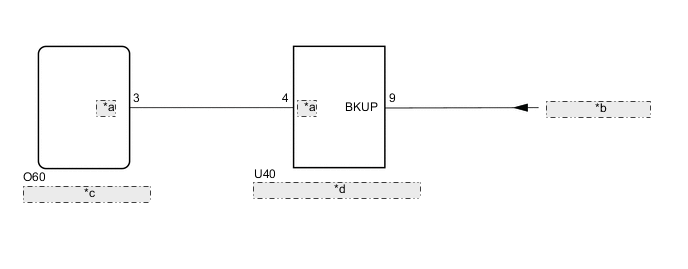
| *a | REV |
| *b | from BKUP LP Relay |
| *c | Multi-display Assembly |
| *d | Luggage Electrical Key Switch |
CAUTION / NOTICE / HINT
Note
-
Depending on the parts that are replaced or operations that are performed during vehicle inspection or maintenance, calibration of other systems as well as the parking assist monitor system may be needed.
-
When "!" is displayed on the multi-display assembly after the cable is disconnected from the negative (-) auxiliary battery terminal, correct the steering angle neutral point.
PROCEDURE
-
INSPECT MULTI-DISPLAY ASSEMBLY (REV)
-
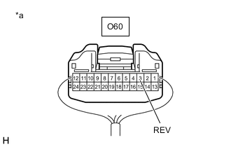
*a Component with harness connected
(Multi-display Assembly)
Measure the voltage according to the value(s) in the table below.
Standard Voltage Tester Connection Condition Specified Condition O60-3 (REV) - Body ground Power switch on (IG), shift lever in R 11 to 14 V Power switch on (IG), shift lever not in R Below 2 V Result Proceed to OK NG
OK 
REPLACE MULTI-DISPLAY ASSEMBLY Click here
NG 
-
-
CHECK HARNESS AND CONNECTOR (MULTI-DISPLAY ASSEMBLY - LUGGAGE ELECTRICAL KEY SWITCH)
-
Disconnect the O60 multi-display assembly connector.
-
Disconnect the U40 luggage electrical key switch connector.
-
Measure the resistance according to the value(s) in the table below.
Standard Resistance Tester Connection Condition Specified Condition O60-3 (REV) - U40-4 (REV) Always Below 1 Ω O60-3 (REV) or U40-4 (REV) - Body ground Always 10 kΩ or higher Result Proceed to OK NG
NG
REPAIR OR REPLACE HARNESS OR CONNECTOR
OK
-
-
INSPECT LUGGAGE ELECTRICAL KEY SWITCH
-
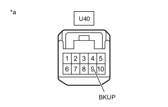
*a Front view of wire harness connector
(Luggage Electrical Key Switch)
Measure the voltage according to the value(s) in the table below.
Standard Voltage Tester Connection Condition Specified Condition U40-9 (BKUP) - Body ground Power switch on (IG), shift lever in R 11 to 14 V Power switch on (IG), shift lever not in R Below 2 V Result Proceed to OK NG
OK
REPLACE LUGGAGE ELECTRICAL KEY SWITCH Click here
NG
PROCEED TO NEXT SUSPECTED AREA SHOWN IN PROBLEM SYMPTOMS TABLE for Triple Beam Headlight: Click here
PROCEED TO NEXT SUSPECTED AREA SHOWN IN PROBLEM SYMPTOMS TABLE for Single Beam Headlight: Click here -