BODY STRUCTURE
-
FUNCTION
-
Impact Absorbing Structure for Front Collision
-
The impact energy from a frontal collision disperses to the left and right front side member sub-assemblies via the front bumper reinforcement sub-assembly. This structure allows the dispersed energy to be efficiently absorbed from the highly strengthened front side member sub-assembly due to the adoption of high strength steel sheets and the straight shape of the entire structure.
-
The use of a large front torque box enables a construction that allows the energy to be efficiently dispersed to the outer rocker reinforcement sub-assembly from the front side member sub-assembly.
-
The attachment of the No. 1 front side member reinforcements to the front floor tunnel section enables a construction that efficiently disperses energy from the front side member sub-assemblies. Furthermore, this structure uses a straight-shaped tunnel section to minimize malformation of the cabin.
-
The use of front floor cross member sub-assemblies enables a construction that enhances support stiffness against impact energy by connections to the left and right outer rocker reinforcement sub-assemblies.
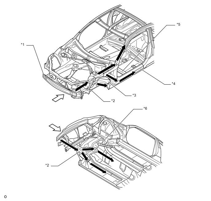
Text in Illustration *1 Front Bumper Reinforcement Sub-assembly *2 Front Side Member Sub-assembly *3 Front Torque Box *4 Outer Rocker Reinforcement Sub-assembly *5 Front Floor Cross Member Sub-assembly *6 No. 1 Front Side Member Reinforcement 
Path of Collision Energy 
Frontal Collision
-
-
Impact Absorbing Structure for Side Collision
-
This structure enables side impact energy to be effectively dispersed to and absorbed by the body frame, including the pillars, roof, rocker panels, and cross members, by optimization of the body frame structure, the use of ultra high strength steel sheets, and high strength steel sheets.
-
The roof has been structured to efficiently transmit impact energy from the center body pillar reinforcement sub-assembly to be absorbed on the opposite side of the vehicle by the use of a roof panel reinforcement.
-
The use of center floor cross member enables a construction that transmits and absorbs impact energy from the center body pillar reinforcement sub-assembly.
-
The use of front floor cross member sub-assembly enables a construction that transmits and absorbs impact energy from the outer rocker reinforcement sub-assembly.
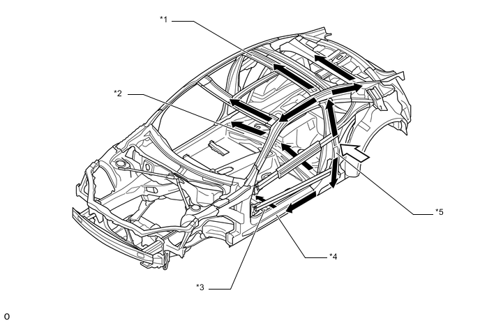
Text in Illustration *1 Roof Panel Reinforcement *2 Center Floor Cross Member *3 Front Floor Cross Member Sub-assembly *4 Outer Rocker Reinforcement Sub-assembly *5 Center Body Pillar Reinforcement Sub-assembly - - Path of Collision Energy Side Collision
-
-
Impact Absorbing Structure for Rear Collision
-
Body malformation is limited by the use of straight high strength rear floor side member sub-assemblies, and impact energy is transmitted to the outer rocker reinforcement sub-assemblies to enable efficient absorption.
-
Impact energy is efficiently transmitted to the center floor cross member by the attachment of front crossmember side gussets to the rear floor side member sub-assemblies and the mounting portions of the center floor cross member, enabling a construction that disperses energy to the tunnel section.
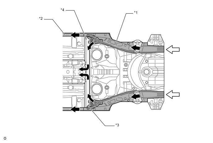
Text in Illustration *1 Rear Floor Side Member Sub-assembly *2 Outer Rocker Reinforcement Sub-assembly *3 Front Crossmember Side Gusset *4 Center Floor Cross Member Path of Collision Energy Rear Collision
-
-
Lessening Pedestrian Injury
-
A front bumper energy absorber and a front bumper stay bracket are provided in the front bumper portion. This structure helps absorb the impact energy applied to the legs of the pedestrians.
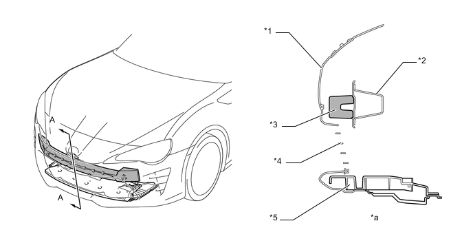
Text in Illustration *1 Front Bumper Cover *2 Front Bumper Reinforcement Sub-assembly *3 Front Bumper Energy Absorber *4 Lower No. 1 Radiator Grille *5 Front Bumper Stay Bracket - - *a A - A Cross Section - - -
The inner hood panel uses a longitudinal ribbed structure to ease impacts to the head during collisions with pedestrians. Stroke has also been maintained between the engine compartment components (e.g. the throttle body with motor assembly) to ease impacts.
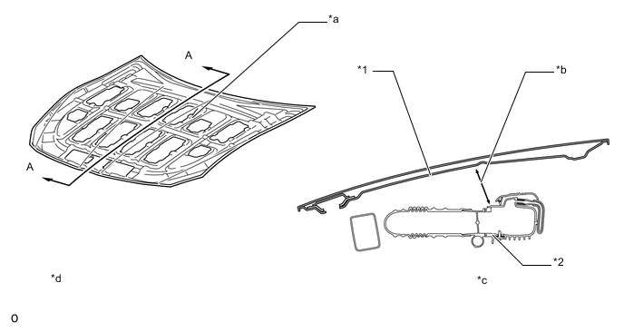
Text in Illustration *1 Inner Hood Panel *2 Throttle Body with Motor Assembly *a Longitudinal Ribbed Structure *b Stroke *c A - A Cross Section *d The Illustration Shows an Example -
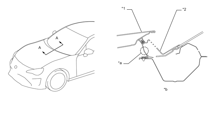
Fender bracket (front fender extension) is used in the joint portion of the front fender (front fender sub-assembly). The height of the fender bracket and the gap between the fender bracket and the fender have been optimized. Also, fold point is provided on the fender brackets. Therefore, during a collision with a pedestrian, the fender brackets absorb impact energy, with the aim of ensuring optimized energy absorption to the pedestrian's head.
Text in Illustration *1 Front Fender Panel (Front Fender Sub-assembly RH) *2 Fender Bracket (Front Fender Extension RH) *a Fold Point - - -
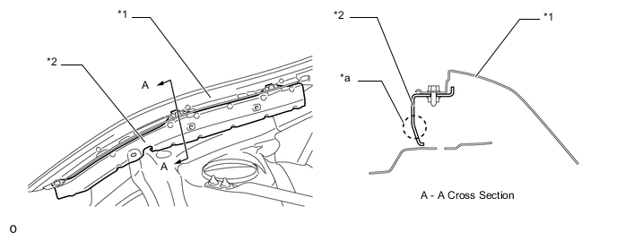
The cowl ventilator louver has been given an open section, providing a crushable structure. The cowl use an open section structure that collapses easily in an impact from the top, thus help reducing the impact to and head injuries sustained by a pedestrian in an accident.
Text in Illustration *1 Hood Panel (Hood Sub-assembly) *2 Cowl Ventilator Louver *a Crushable Structure *b A - A Cross Section
-
-
Aerodynamics
-
The shape of the lower edge of the front bumper cover has been optimized to increase the rectifying effect on the airflow beneath the vehicle floor, helping achieve excellent handling stability.
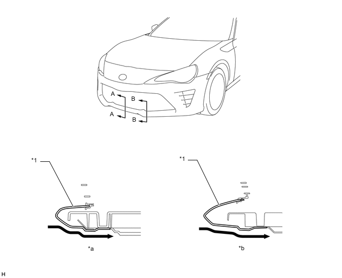
Text in Illustration *1 Front Bumper Cover - - *a A - A Cross Section *b B - B Cross Section Airflow - - -
An aero stabilizing fin is provided on the rear combination light for enhanced aerodynamics.
-
After passing the aero stabilizing fin, the air speed will increase and vortex flow will be generated.
-
This vortex flow increases the speed of surrounding air while at the same time pulling the airflow towards the vehicle body.
-
The airflow with higher speed passes near both sides of the vehicle body and ends at the rear of the vehicle. This helps to hold the vehicle body, and thus stabilizes the vehicle.
-
-
The shape of the lower edge of the rear bumper has been optimized, in order to rectify the airflow toward the rear of the vehicle, helping achieve excellent handling stability.
-
A rear spoiler has been installed to rectify the airflow toward the rear of the vehicle and ensure straight-line stability during high-speed driving.
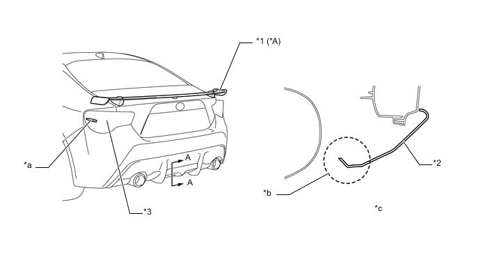
Text in Illustration *A Models with Rear Spoiler - - *1 Rear Spoiler *2 Rear Bumper Cover *3 Rear Combination Light - - *a Aero Stabilizing Fin *b for Airflow Management *c A - A Cross Section - - -
Spats are fitted at the front of the front and rear tires to direct the air flow, and this helps reduce air turbulence into the wheel house, leading to excellent straight driving stability at high speeds.
-
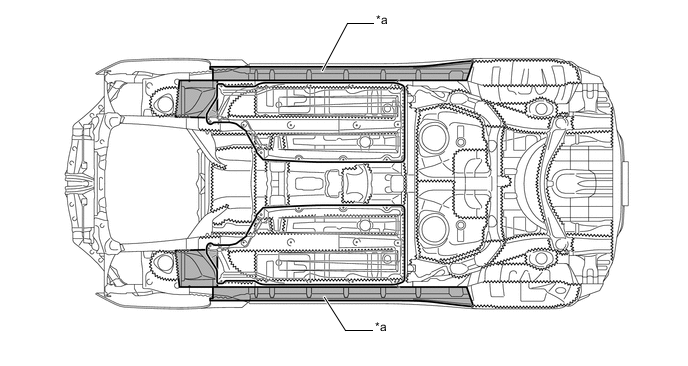
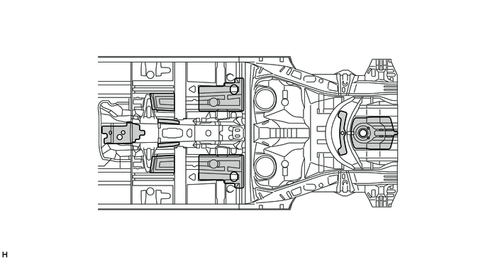
The height, angle, and shape of the engine under cover and the floor covers have been optimized, and the location and shape of the covers for chassis, fuel system, and exhaust parts have been optimized, resulting in smooth airflow underneath the floor.
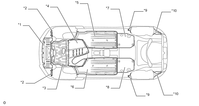
Text in Illustration *1 Front Lower Bumper Cover *2 Front Spats (Front Wheel Opening Extension Pad) *3 No. 1 Engine Under Cover *4 No. 2 Engine Under Cover *5 Rear Engine Under Cover LH *6 Rear Engine Under Cover *7 No. 2 Fuel Tank Protector *8 No. 1 Fuel Tank Protector *9 Rear Spats (Front Rear Wheel House Plate) *10 Rear Bumper Side Seal
-
-
-
CONSTRUCTION
-
Light Weight and Highly Rigid Body
-
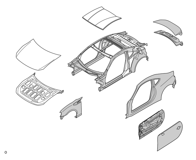
High strength steel sheet and ultra high strength steel sheet are used in order to achieve excellent body rigidity and a lightweight body.
-
Aluminum is used in the hood panel, resulting in light weight.
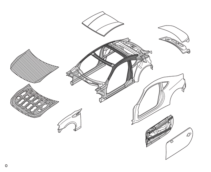
Text in Illustration (Upper Body: ) 
Ultra High Strength Steel Sheet 
High Strength Steel Sheet 
Aluminum - - 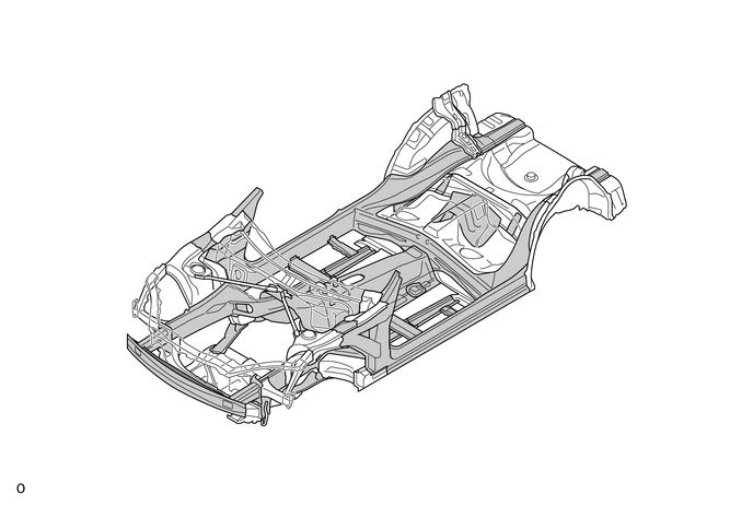
Text in Illustration (Under Body: ) Ultra High-strength Steel Sheet High-strength Steel Sheet
-
-
Body Shell Construction
-
A lightweight body structure with high rigidity is achieved by combining the front top mount and the dash panel sub-assembly with V-shaped front suspension upper to cowl brace sub-assemblies.
-
Large front gussets (cowl top side panel) have been attached, and the front top mount and front pillar have been firmly connected to enhance rigidity and smoothly transmit force to outer rocker reinforcement sub-assemblies.
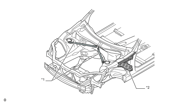
Text in Illustration *1 Front Suspension Upper to Cowl Brace Sub-assemblies *2 Cowl Top Side Panel -
The rear frame (rear floor side member sub-assemblies) and the outer rocker reinforcement sub-assemblies are joined, with rear gussets (front crossmember side gussets) attached at the mounting portion to enhance rigidity.
-
Gussets are attached to the wheel houses to provide rigidity to the rear top mount.
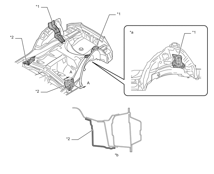
Text in Illustration *1 Gusset *2 Front Crossmember Side Gusset *a The Illustration Shows a Left Side *b A - A Cross Section
-
-
Anti-corrosion steel sheet
-
Anti-corrosion steel sheet is used as in the following illustration.
Text in Illustration (Upper Body: ) Anti-corrosion steel sheet Anti-corrosion steel sheet (Plating) 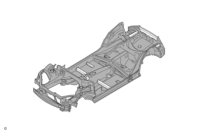
Text in Illustration (Under Body: ) Anti-corrosion steel sheet - -
-
-
Under Coat
-
A PVC coating is applied to the underside of the body, which is susceptible to chipping, achieving excellent anti-rust performance.
Text in Illustration (Under Floor: ) *a Under Floor Side - - 
Edge Seal Under Coating Area
-
-
Anti-chipping Application
-
Chipping-resistant tape is attached to the quarter panels.
-
To protect the paint from chipping, anti-chipping paint is applied to the front end of the hood panel and the front end of the roof panel.
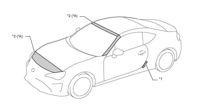
Text in Illustration *A Models with Anti-chipping Paint - - *1 Chipping Seal *2 Anti-chipping Paint
-
-
Low Vibration and Low Noise Body
-
A dash panel insulator assembly, front floor pad and transmission cover have each been attached to reduce the amount of noise that leaks into the vehicle cabin.
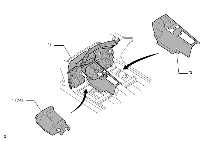
Text in Illustration *A Models with Transmission Cover - - *1 Dash Panel Insulator Assembly *2 Front Floor Pad *3 Transmission Cover - - -
A hood insulator is attached to the hood sub-assembly to effectively absorb mechanical engine noise.
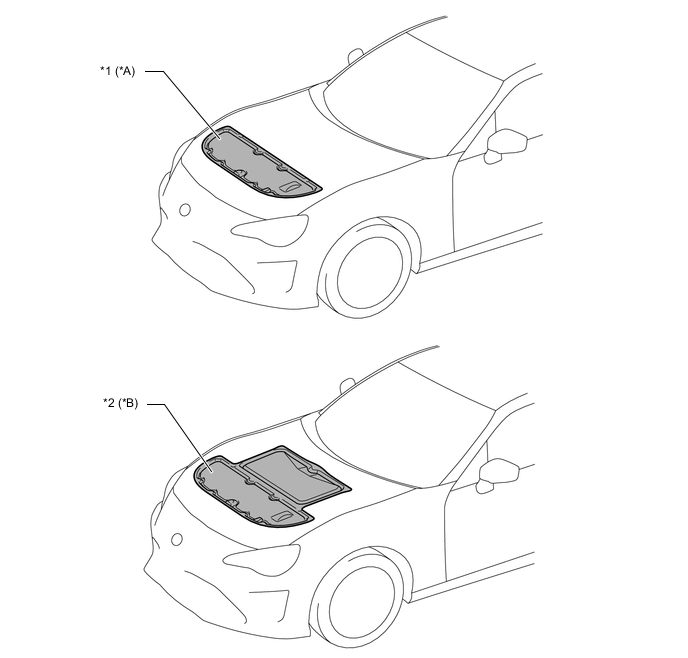
Text in Illustration *A Models with Hood Insulator *B Models with Hood Insulator (Large Type) *1 Hood Insulator *2 Hood Insulator (Large Type) -
Effective positioning of asphalt sheets (floor silencers) on the floor panel minimizes the sound transmitted from the engine and tires.
Text in Illustration (Floor: ) Floor Silencer - - -
Outside Windshield Molding is used, reducing steps between the windshield glass and roof panel to reduce wind noise.
-
No. 2 front door weatherstrip has been attached to make tight contact with the front door glass sub-assembly, to reduce the amount of noise that leaks into the vehicle cabin.
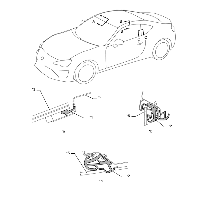
Text in Illustration *1 Outside Windshield Molding *2 No. 2 Front Door Weatherstrip LH *3 Windshield Glass *4 Roof Panel *5 Front Door Glass Sub-assembly - - *a A - A Cross Section *b B - B Cross Section *c C - C Cross Section - -
-
-
Parts with Low Repair Cost
-
The front bumper reinforcement sub-assembly and radiator support (frame section) are structured to use bolts for attachment to enable the replacement of damaged parts, thereby improving serviceability and reducing the cost of part replacement.
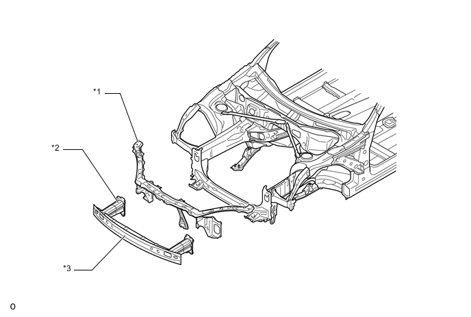
Text in Illustration *1 Radiator Support (Frame Section) *2 Crash Box *3 Front Bumper Reinforcement Sub-assembly - - -
Rear bumper reinforcement is connected to the body lower back panel sub-assembly using bolts to improve the ease of repairs and replacement.
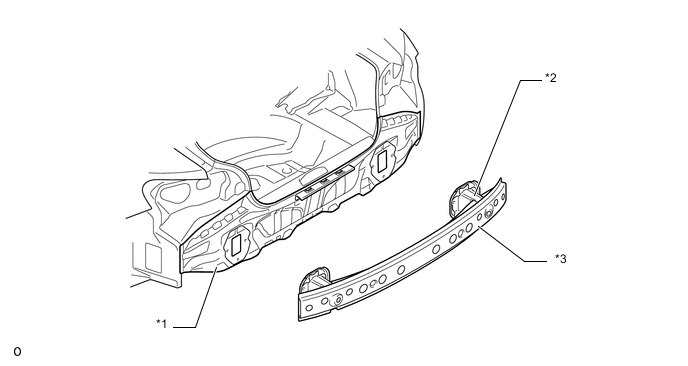
Text in Illustration (Models for China and Korea and G.C.C. Countries Package: )( - 2017/10) *1 Body Lower Back Panel Sub-assembly *2 Crash Box *3 Rear Bumper Reinforcement - - 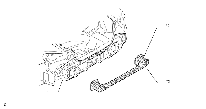
Text in Illustration (Except Models for China and Korea and G.C.C. Countries Package: )( - 2017/10) *1 Body Lower Back Panel Sub-assembly *2 Crash Box *3 Rear Bumper Reinforcement - -
Text in Illustration (Models for Korea and G.C.C. Countries Package: )(2017/10 - ) *1 Body Lower Back Panel Sub-assembly *2 Crash Box *3 Rear Bumper Reinforcement - -
Text in Illustration (Except Models for Korea and G.C.C. Countries Package: )(2017/10 - ) *1 Body Lower Back Panel Sub-assembly *2 Crash Box *3 Rear Bumper Reinforcement - -
-
-