POWER DOOR LOCK CONTROL SYSTEM Only Back Door cannot be Opened
| DTC Code | DTC Name |
|---|---|
| Only Back Door cannot be Opened |
DESCRIPTION
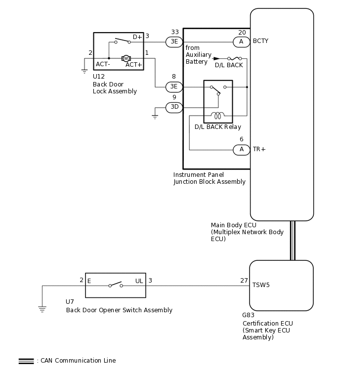
The main body ECU (multiplex network body ECU) receives signals from the back door opener switch assembly. Then, the main body ECU (multiplex network body ECU) activates the back door lock motor.
WIRING DIAGRAM
CAUTION / NOTICE / HINT
The power door lock control system uses the CAN communication system. Inspect the communication function by following How to Proceed with Troubleshooting. Troubleshoot the power door lock control system after confirming that the communication systems are functioning properly.
Before performing this troubleshooting, perform troubleshooting for "Back Door Entry Unlock Function does not Operate" for the Entry and start system (for Entry Function) first.
Inspect the fuses for circuits related to this system before performing the following inspection procedure.
When replacing the main body ECU (multiplex network body ECU), make sure to replace it with a new one.
PROCEDURE
INSPECT BACK DOOR LOCK ASSEMBLY
Remove the back door lock assembly.
Inspect the back door lock assembly.
Result
Proceed to
OK
NG
CHECK HARNESS AND CONNECTOR (BACK DOOR LOCK ASSEMBLY - INSTRUMENT PANEL JUNCTION BLOCK ASSEMBLY AND BODY GROUND)
Disconnect the 3E instrument panel junction block assembly connector.
Measure the resistance according to the value(s) in the table below.
Standard Resistance
Tester Connection
Condition
Specified Condition
U12-1 (ACT+) - 3E-8 (TR+)
Always
Below 1 Ω
U12-3 (D+) - 3E-33 (BCTY)
U12-2 (ACT-) - Body ground
U12-1 (ACT+) or 3E-8 (TR+) - Body ground
Always
10 kΩ or higher
U12-3 (D+) or 3E-33 (BCTY) - Body ground
Result
Proceed to
OK
NG
NG REPAIR OR REPLACE HARNESS OR CONNECTOR
CHECK INSTRUMENT PANEL JUNCTION BLOCK ASSEMBLY
Remove the instrument panel junction block assembly.
for LHD:Click here
for RHD:Click here
Remove the main body ECU (multiplex network body ECU) from the instrument panel junction block assembly.
Measure the resistance according to the value(s) in the table below.
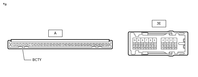
*a
Component without harness connected
(Instrument Panel Junction Block Assembly)
-
-
Standard Resistance
Tester Connection
Condition
Specified Condition
A-20 (BCTY) - 3E-33
Always
Below 1 Ω
Result
Proceed to
OK
NG
CHECK INSTRUMENT PANEL JUNCTION BLOCK ASSEMBLY (D/L BACK RELAY)
Disconnect the instrument panel junction block assembly connector.
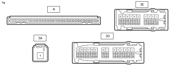
*a
Front view of wire harness connector
(to Instrument Panel Junction Block Assembly)
-
-
Measure the resistance according to the value(s) in the table below.
Standard Resistance
Tester Connection
Condition
Specified Condition
3D-9 - 3E-8
Auxiliary battery voltage applied to terminals 3A-1 and A-6
10 kΩ or higher
3D-9 - 3E-8
Auxiliary battery voltage not applied to terminals 3A-1 and A-6
Below 1 Ω
Measure the voltage according to the value(s) in the table below.
Standard Voltage
Tester Connection
Condition
Specified Condition
3E-8 - Auxiliary battery negative (-) terminal
Auxiliary battery voltage applied to terminals 4F-1 and A-6
11 to 14 V
Result
Proceed to
OK
NG