CAN COMMUNICATION SYSTEM(w/ Central Gateway ECU) Central Gateway ECU Communication Stop Mode
DESCRIPTION
| Detection Item | Symptom | Trouble Area |
|---|---|---|
| Central Gateway ECU Communication Stop Mode | Either condition is met:
|
|
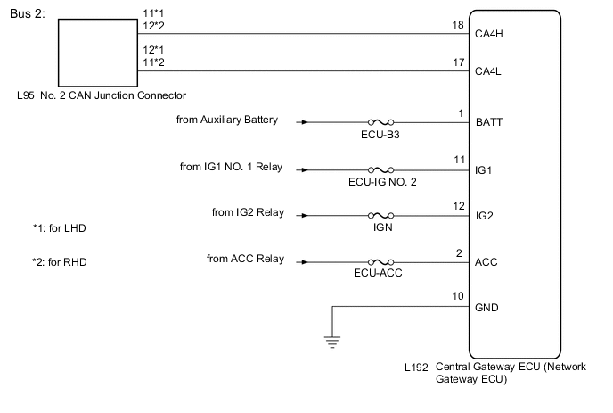
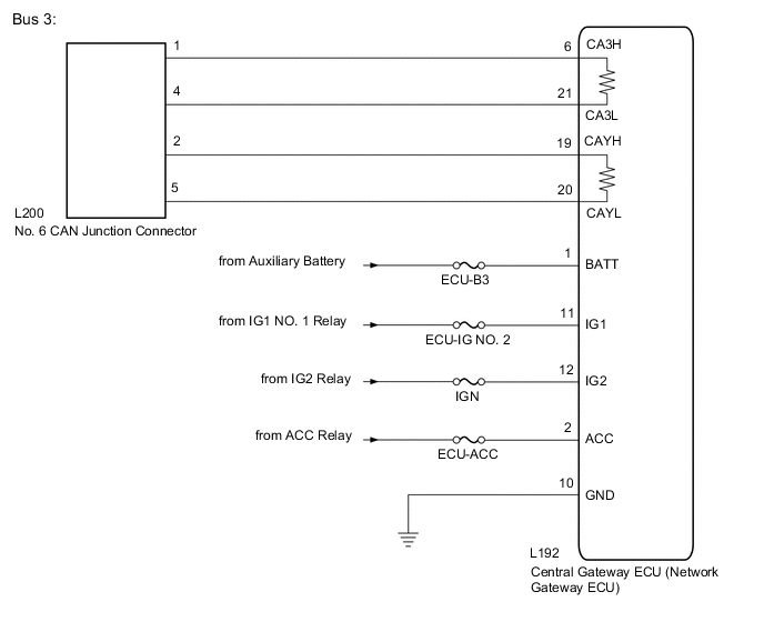
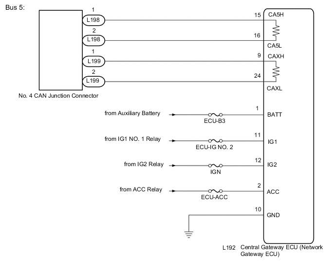
WIRING DIAGRAM
CAUTION / NOTICE / HINT
Note
-
Before measuring the resistance of the CAN bus, turn the power switch off and leave the vehicle for 1 minute or more without operating the key or any switches, or opening or closing the doors. After that, disconnect the cable from the negative (-) auxiliary battery terminal and leave the vehicle for 1 minute or more before measuring the resistance.
-
After turning the power switch off, waiting time may be required before disconnecting the cable from the negative (-) auxiliary battery terminal. Therefore, make sure to read the disconnecting the cable from the negative (-) auxiliary battery terminal notices before proceeding with work Click here).
-
Because the order of diagnosis is important to allow correct diagnosis, make sure to begin troubleshooting using How to Proceed with Troubleshooting when CAN communication system related DTCs are output Click here.
-
After the repair, perform the CAN bus check and check that all the ECUs and sensors connected to the CAN communication system are displayed Click here.
-
Inspect the fuses for circuits related to this system before performing the following procedure.
Tech Tips
-
Before disconnecting related connectors for inspection, push in on each connector body to check that the connector is not loose or disconnected.
-
When a connector is disconnected, check that the terminals and connector body are not cracked, deformed or corroded.
PROCEDURE
-
CHECK HARNESS AND CONNECTOR (POWER SOURCE CIRCUIT)
-
Disconnect the cable from the negative (-) auxiliary battery terminal.
-
Disconnect the L192 central gateway ECU (network gateway ECU) connector.
-
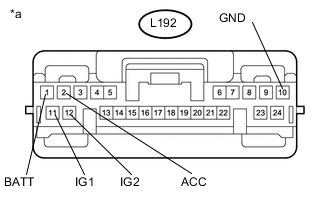
Text in Illustration *a Front view of wire harness connector
(to Central Gateway ECU (Network Gateway ECU))
Measure the resistance according to the value(s) in the table below.
Standard Resistance Tester Connection Condition Specified Condition L192-10 (GND) - Body ground Cable disconnected from negative (-) auxiliary battery terminal Below 1 Ω -
Reconnect the cable to the negative (-) auxiliary battery terminal.
-
Measure the voltage according to the value(s) in the table below.
Standard Voltage Tester Connection Condition Specified Condition L192-1 (BATT) - Body ground Power switch off 11 to 14 V L192-2 (ACC) - Body ground Power switch on (ACC) 11 to 14 V L192-11 (IG1) - Body ground Power switch on (IG) 11 to 14 V L192-12 (IG2) - Body ground Power switch on (IG) 11 to 14 V
NG 
REPAIR OR REPLACE HARNESS OR CONNECTOR (POWER SOURCE CIRCUIT)
OK 
-
-
CHECK FOR OPEN IN CAN BUS LINES (CENTRAL GATEWAY ECU (NETWORK GATEWAY ECU))
-
Disconnect the cable from the negative (-) auxiliary battery terminal.
-
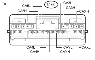
Text in Illustration *a Front view of wire harness connector
(to Central Gateway ECU (Network Gateway ECU))
Measure the resistance according to the value(s) in the table below.
Standard Resistance Bus 2 Branch Line Tester Connection Condition Specified Condition L192-18 (CA4H) - L192-17 (CA4L) Cable disconnected from negative (-) auxiliary battery terminal 54 to 69 Ω Bus 3 Main Line Tester Connection Condition Specified Condition L192-6 (CA3H) - L192-19 (CAYH) Cable disconnected from negative (-) auxiliary battery terminal Below 1 Ω L192-21 (CA3L) - L192-20 (CAYL) Cable disconnected from negative (-) auxiliary battery terminal Below 1 Ω Bus 5 Main Line Tester Connection Condition Specified Condition L192-15 (CA5H) - L192-9 (CAXH) Cable disconnected from negative (-) auxiliary battery terminal Below 1 Ω L192-16 (CA5L) - L192-24 (CAXL) Cable disconnected from negative (-) auxiliary battery terminal Below 1 Ω Result Result Proceed to OK A NG (Bus 2 Branch line) B NG (Bus 3 Main line) C NG (Bus 5 Main line) D
A
REPLACE CENTRAL GATEWAY ECU (NETWORK GATEWAY ECU) Click here
B
REPAIR OR REPLACE CAN BRANCH LINES OR CONNECTOR (CENTRAL GATEWAY ECU (NETWORK GATEWAY ECU))
D 
CHECK FOR OPEN IN CAN BUS LINES (NO. 4 CAN JUNCTION CONNECTOR) Click here
C
-
-
CHECK FOR OPEN IN CAN BUS LINES (NO. 6 CAN JUNCTION CONNECTOR)
-
Reconnect the L192 central gateway ECU (network gateway ECU) connector.
-
Disconnect the L200 No. 6 CAN junction connector.
-
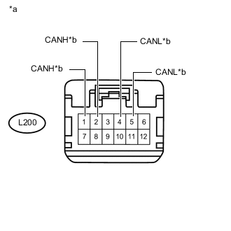
Text in Illustration *a Front view of wire harness connector
(to No. 6 CAN Junction Connector)
*b to Central Gateway ECU (Network Gateway ECU) Measure the resistance according to the value(s) in the table below.
Standard Resistance Tester Connection Condition Specified Condition Connected to L200-1 (CANH) - L200-4 (CANL) Cable disconnected from negative (-) auxiliary battery terminal 108 to 132 Ω Central gateway ECU (network gateway ECU) (CA3H and CA3L terminal) L200-2 (CANH) - L200-5 (CANL) Cable disconnected from negative (-) auxiliary battery terminal 108 to 132 Ω Central gateway ECU (network gateway ECU) (CAYH and CAYL terminal)
OK
REPLACE NO. 6 CAN JUNCTION CONNECTOR
NG
REPAIR OR REPLACE CAN MAIN BUS LINES OR CONNECTOR (CENTRAL GATEWAY ECU (NETWORK GATEWAY ECU) - NO. 6 CAN JUNCTION CONNECTOR)
-
-
CHECK FOR OPEN IN CAN BUS LINES (NO. 4 CAN JUNCTION CONNECTOR)
-
Reconnect the L192 central gateway ECU (network gateway ECU) connector.
-
Disconnect the L198 and L199 No. 4 CAN junction connectors.
-
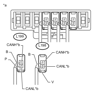
Text in Illustration *a Front view of wire harness connector
(to No. 4 CAN Junction Connector)
*b to Central Gateway ECU (Network Gateway ECU) Measure the resistance according to the value(s) in the table below.
Standard Resistance Tester Connection Condition Specified Condition Connected to L198-1 (CANH) - L198-2 (CANL) Cable disconnected from negative (-) auxiliary battery terminal 108 to 132 Ω Central gateway ECU (network gateway ECU) (CA5H and CA5L terminal) L199-1 (CANH) - L199-2 (CANL) Cable disconnected from negative (-) auxiliary battery terminal 108 to 132 Ω Central gateway ECU (network gateway ECU) (CAXH and CAXL terminal)
OK
REPLACE NO. 4 CAN JUNCTION CONNECTOR
NG
REPAIR OR REPLACE CAN MAIN BUS LINES OR CONNECTOR (NO. 4 CAN JUNCTION CONNECTOR - CENTRAL GATEWAY ECU (NETWORK GATEWAY ECU))
-