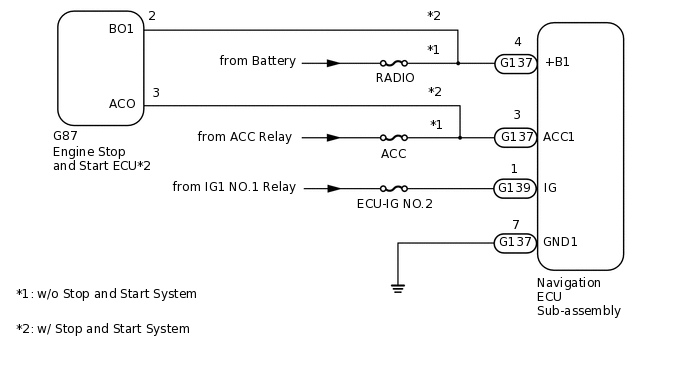
NAVIGATION SYSTEM(for HDD) Navigation Receiver Assembly Power Source Circuit
| DTC Code | DTC Name |
|---|---|
| Navigation Receiver Assembly Power Source Circuit |
DESCRIPTION
Inspect the fuses for circuits related to this system before performing the following inspection procedure.
WIRING DIAGRAM
CAUTION / NOTICE / HINT
Inspect the fuses for circuits related to this system before performing the following inspection procedure.
PROCEDURE
CONFIRM MODEL
Choose the model to be inspected.
Result
Proceed to
w/o Stop and Start System
w/ Stop and Start System
w/ Stop and Start System CHECK HARNESS AND CONNECTOR (NAVIGATION ECU SUB-ASSEMBLY - ENGINE STOP AND START ECU)Click here
CHECK HARNESS AND CONNECTOR (NAVIGATION ECU SUB-ASSEMBLY - BATTERY AND BODY GROUND)
-
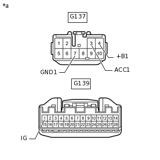
*a
Front view of wire harness connector
(to Navigation ECU Sub-assembly)
Disconnect the navigation ECU sub-assembly connectors.
Measure the resistance according to the value(s) in the table below.
Standard Resistance
Tester Connection
Condition
Specified Condition
G137-7 (GND1) - Body ground
Always
Below 1 Ω
Measure the voltage according to the value(s) in the table below.
Standard Voltage
Tester Connection
Condition
Specified Condition
G137-4 (+B1) - G137-7 (GND1)
Always
11 to 14 V
G137-3 (ACC1) - G137-7 (GND1)
Ignition switch ACC
11 to 14 V
G139-1 (IG) - G137-7 (GND1)
Ignition switch ON
11 to 14 V
Result
Proceed to
OK
NG
NG REPAIR OR REPLACE HARNESS OR CONNECTOR
-
CHECK HARNESS AND CONNECTOR (NAVIGATION ECU SUB-ASSEMBLY - ENGINE STOP AND START ECU)
Disconnect the G137 navigation ECU sub-assembly connector.
Disconnect the G87 engine stop and start ECU connector.
Measure the resistance according to the value(s) in the table below.
Standard Resistance
Tester Connection
Condition
Specified Condition
G137-3 (ACC1) - G87-3 (ACO)
Always
Below 1 Ω
G137-4 (+B1) - G87-2 (BO1)
Always
Below 1 Ω
G137-3 (ACC1) - Body ground
Always
10 kΩ or higher
G137-4 (+B1) - Body ground
Always
10 kΩ or higher
Result
Proceed to
OK
NG
NG REPAIR OR REPLACE HARNESS OR CONNECTOR
CHECK ENGINE STOP AND START ECU
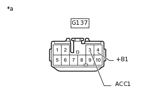
*a
Front view of wire harness connector
(to Navigation ECU Sub-assembly)
Disconnect the navigation ECU sub-assembly connector.
Measure the voltage according to the value(s) in the table below.
Standard Voltage
Tester Connection
Condition
Specified Condition
G137-3 (ACC1) - Body ground
Ignition switch ACC
10.5 to 14 V
G137-4 (+B1) - Body ground
Always
10.5 to 14 V
Result
Proceed to
OK
NG
CHECK HARNESS AND CONNECTOR (NAVIGATION ECU SUB-ASSEMBLY - BATTERY AND BODY GROUND)
-
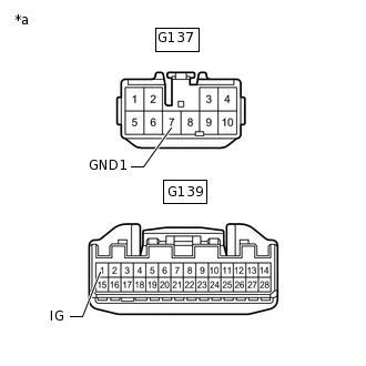
*a
Front view of wire harness connector
(to Navigation ECU Sub-assembly)
Disconnect the navigation ECU sub-assembly connectors.
Measure the resistance according to the value(s) in the table below.
Standard Resistance
Tester Connection
Condition
Specified Condition
G137-7 (GND1) - Body ground
Always
Below 1 Ω
Measure the voltage according to the value(s) in the table below.
Standard Voltage
Tester Connection
Switch Condition
Specified Condition
G139-1 (IG) - G137-7 (GND1)
Ignition switch ON
11 to 14 V
Result
Proceed to
OK
NG
NG REPAIR OR REPLACE HARNESS OR CONNECTOR
-