DECELERATION SENSOR INSPECTION
PROCEDURE
CHECK DECELERATION SENSOR
Check the deceleration sensor.
Under any of the following conditions, replace the sensor with a new one.
The surface of the sensor is cracked, dented, or chipped off.
The connector or wire harness is scratched, cracked, or damaged.
The sensor has been dropped.
INSPECT DECELERATION SENSOR
-
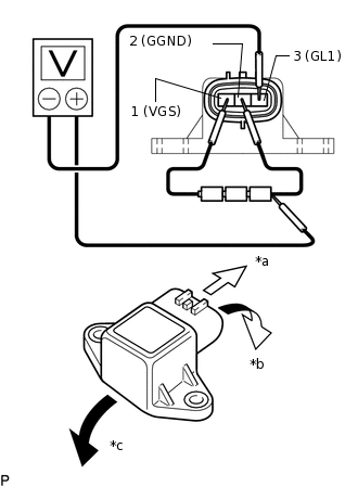
*a
Front
*b
Forward
*c
Rearward
Connect 3 dry cell batteries of 1.5 V in series (approximately 4.5 V total).
Connect the batteries' positive (+) lead to terminal 1 (VGS) and the negative (-) lead to terminal 2 (GGND).
Note:Do not apply 6 V or higher to terminals 1 (VGS) and 2 (GGND).
Connect the voltmeter's positive (+) lead to the negative (-) lead of the batteries, and the negative (-) lead to terminal 3 (GL1).
Check the output voltage of terminal 3 (GL1) when the sensor is tilted forward and rearward.
Standard voltage
Tester Connection
Sensor Position
Specified Condition
3 (GL1) - Battery's negative (-) lead
Horizontal
Approx. 2.25 V
3 (GL1) - Battery's negative (-) lead
Tilted forward
Approx. 0.45 to 2.25 V
3 (GL1) - Battery's negative (-) lead
Tilted rearward
Approx. 2.25 to 4.05 V
If the result is not as specified, replace the deceleration sensor.
Tip:If voltage drops, the sensor should be replaced with a new one.
When replacing the sensor, it should not be placed upside down.
-