FRONT BRAKE(for 17 inch Front Disc Brake) INSTALLATION
CAUTION / NOTICE / HINT
Use the same procedure for the RH and LH sides.
The following procedure is for the LH side.
When the brake pedal is first depressed after replacing the brake pads or pushing back the disc brake piston, DTC C1214 may be output. As there is no malfunction, clear the DTCs.
PROCEDURE
INSTALL FRONT DISC
-
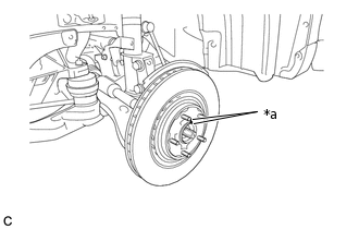
*a
Matchmark
Align the matchmarks and install the front disc.
Tip:When replacing the front disc with a new one, select the installation position where the front disc has smallest runout.
-
INSTALL FRONT DISC BRAKE CYLINDER MOUNTING LH
Install the front disc brake cylinder mounting LH with the 2 bolts.
106.8 N*m
1089 kgf*cm
79 ft.*lbf
INSTALL FRONT DISC BRAKE BUSH DUST BOOT
-
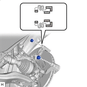

Lithium soap base glycol grease
Apply a light coat of lithium soap base glycol grease to the entire circumference of 2 new front disc brake bush dust boots, and the entire inner circumference of both ends.
Tip:Apply at least 0.3 g (0.01 oz.) of lithium soap base glycol grease to the front disc brake bush dust boot.
Install the 2 front disc brake bush dust boots to the front disc brake cylinder mounting LH.
-
INSTALL FRONT DISC BRAKE CYLINDER SLIDE PIN
-
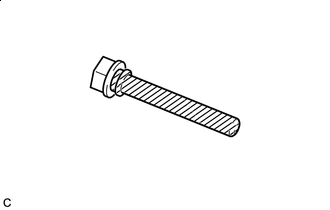
Lithium soap base glycol grease
Apply a light coat of lithium soap base glycol grease to the sliding part and the seal surface of the front disc brake cylinder slide pin.
-
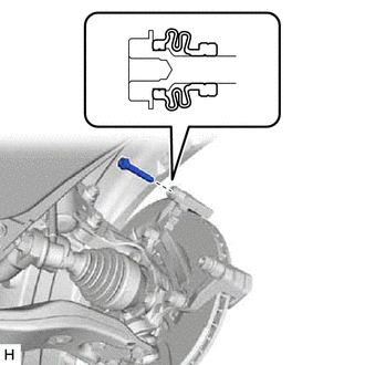
Install the front disc brake cylinder slide pin to the front disc brake cylinder mounting LH.
Push the front disc brake cylinder slide pin into the front disc brake bush dust boot to align them.
-
INSTALL FRONT DISC BRAKE CYLINDER SLIDE BUSH
-
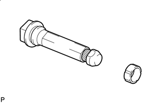
Lithium soap base glycol grease
Apply a light coat of lithium soap base glycol grease to the contact surface of the front No. 2 disc brake cylinder slide pin where it contacts the front disc brake cylinder slide bush.
Install a new front disc brake cylinder slide bush to the front No. 2 disc brake cylinder slide pin.
-
INSTALL NO. 2 DISC BRAKE CYLINDER SLIDE PIN
-
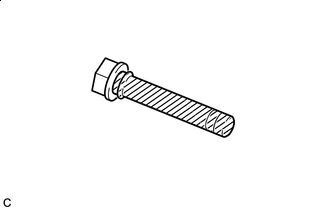
Lithium soap base glycol grease
Apply a light coat of lithium soap base glycol grease to the sliding part and the seal surface of the front No. 2 disc brake cylinder slide pin.
-
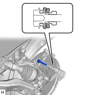
Install the front No. 2 disc brake cylinder slide pin to the front disc brake cylinder mounting LH.
Push the front No. 2 disc brake cylinder slide pin into the front disc brake bush dust boot to align them.
-
INSTALL FRONT NO. 1 DISC BRAKE PAD SUPPORT PLATE
-
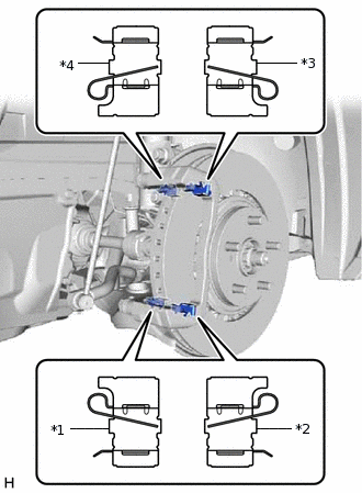
*1
Front No. 1 Disc Brake Pad Support Plate
*2
Front No. 2 Disc Brake Pad Support Plate
*3
Front No. 3 Disc Brake Pad Support Plate
*4
Front No. 4 Disc Brake Pad Support Plate
Install the 4 front disc brake pad support plates to the front disc brake cylinder mounting LH as shown in the illustration.
Note:The shapes of the front disc brake pad support plates differ. Therefore, when replacing a front disc brake pad support plate with a new plate, make sure to check the part number and shape for the installation position prior to installation.
When reusing a front disc brake pad support plate, make sure to check the installation position using the matchmark placed during removal prior to installation.
-
INSTALL FRONT NO. 2 DISC BRAKE PAD SUPPORT PLATE
INSTALL FRONT NO. 3 DISC BRAKE PAD SUPPORT PLATE
INSTALL FRONT NO. 4 DISC BRAKE PAD SUPPORT PLATE
INSTALL NO. 1 PAD WEAR INDICATOR PLATE
-
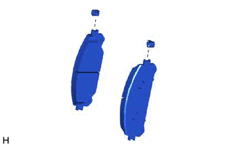
Install the 2 new No. 1 pad wear indicator plates to the 2 front disc brake pads.
Note:Install the No. 1 pad wear indicator plates in the correct positions and directions.
-
INSTALL FRONT ANTI-SQUEAL SHIM KIT
-
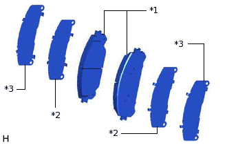
*1
Front Disc Brake Pad
*2
No. 1 Anti-squeal Shim
*3
No. 2 Anti-squeal Shim
Install the 2 No. 1 anti-squeal shims and 2 No. 2 anti-squeal shims to the each pad.
Note:When replacing a worn pad, the shims must be replaced together with the pad.
Install the shims in the correct positions and direction as shown in the illustration.
-
INSTALL FRONT DISC BRAKE PAD
Install the 2 front disc brake pads with the 2 No. 1 anti-squeal shims to the front disc brake cylinder mounting LH.
-
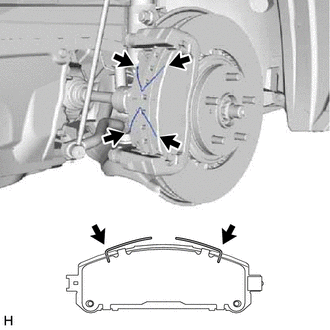
Install the 2 anti-squeal springs to the front disc brake pads.
Note:When replacing the front disc brake pads with new ones, make sure to replace the anti-squeal springs at the same time.
Be sure to install the anti-squeal springs into the front disc brake pad installation holes as far as they will go.
INSTALL DISC BRAKE CYLINDER ASSEMBLY LH
-
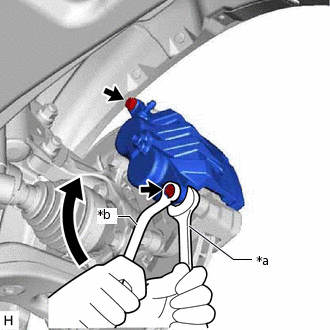
*a
Hold
*b
Turn
Hold the front disc brake cylinder slide pin and install the disc brake cylinder assembly LH to the disc brake cylinder mounting LH with 2 bolts.
34.3 N*m
350 kgf*cm
25 ft.*lbf
Note:Install the disc brake cylinder assembly LH while holding both of the front disc brake pads because the anti-squeal springs may fall off the front disc brake pads.
Be sure that the anti-squeal springs are installed to the front disc brake pads.
-
CONNECT FRONT FLEXIBLE HOSE
Connect the front flexible hose to the disc brake cylinder assembly LH with a new gasket and a new union bolt.
29.4 N*m
300 kgf*cm
22 ft.*lbf
Note:Install the front flexible hose lock securely in the lock hole in the disc brake cylinder assembly LH.
CONNECT CABLE TO NEGATIVE AUXILIARY BATTERY TERMINAL
Connect the cable to the negative (-) auxiliary battery terminal.
Perform the following procedure if air bleeding is not necessary.
Connect the reservoir level switch connector.
Clear the DTCs.
INSTALL BATTERY SERVICE COVER
INSTALL DECK BOARD ASSEMBLY
BLEED BRAKE LINE
INSTALL FRONT WHEEL