METER / GAUGE SYSTEM
-
OUTLINE
-
Combination Meter Sub-assembly
-
A Vacuum Fluorescent Display (VFD) type combination meter sub-assembly or Vacuum Fluorescent Display (VFD) combination meter sub-assembly with a Thin Film Transistor (TFT) type multi-information display is provided depending on the model.
-
Light Emitting Diodes (LEDs) are used for the indicator lights and warning lights.
-
A Hybrid System Indicator is provided in the combination meter sub-assembly. It indicates the output and regeneration conditions of the hybrid system and has an Eco Drive Indicator Zone Display that shows the ratio of Eco-friendly driving.
-
A warning buzzer is provided in the combination meter sub-assembly to sound such as when a seat belt is unfastened or when the vehicle is reversing.
-
The meter ECU (meter circuit plate), mounted in the combination meter sub-assembly, receives signals from ECUs and sensors and shows vehicle information.
Figure 1. Models with Multi-information Display (LHD Models)
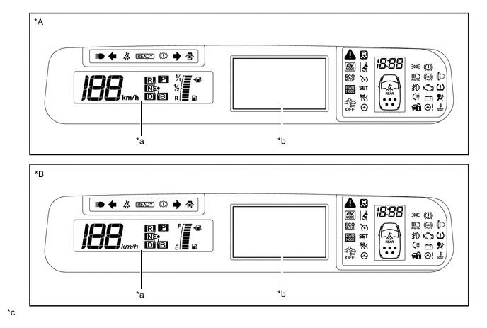
*A Models for Europe *B Destination Package for Taiwan *a Vacuum Fluorescent Display (VFD) *b Thin Film Transistor (TFT) Multi-information Display *c The illustrations shown are examples only. - - Figure 2. Models with Multi-information Display (RHD Models)
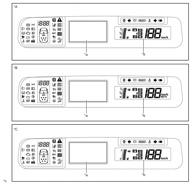
*A Models for Europe *B Destination Package for United Kingdom *C Models for Australia - - *a Thin Film Transistor (TFT) Multi-information Display *b Vacuum Fluorescent Display (VFD) *c The illustrations shown are examples only. - - Figure 3. Except Models with Multi-information Display
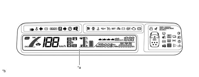
*a Vacuum Fluorescent Display (VFD) *b The illustrations shown are examples only.
-
-
Headup Display
-
A blue-green, dot-matrix type headup display is provided, which is a highly visible information indication tool and minimizes the movement of the driver's line of sight.
-
A windshield glass structure that eliminates a combiner from the display area is employed.
-
-
-
MAIN FEATURES
-
Hybrid System Indicator
-
The Hybrid System Indicator displays the total of the HV battery and engine output as the hybrid system output.
-
The scale for the Hybrid System Indicator is divided into 3 areas (Charge, Eco, Power). The role of each area is as follows.
Area Function Charge (CHG) Charge area indicates when energy regeneration is occurring. Eco
-
Eco area indicates when the vehicle is being driven Eco-friendly.
-
Hybrid Eco area indicates that the vehicle is driven in a manner that promotes frequent motor only operation (Based on various conditions, the hybrid vehicle control ECU determines if the engine should be stopped to enhance fuel efficiency.).
Power (PWR) Power area indicates that the Eco-friendly driving range is being exceeded (during full power driving etc.). -
-
When the Hybrid System Indicator is in the Charge or Eco areas, the Eco Driving Indicator light illuminates to inform the driver that the vehicle is being driven in an Eco-friendly manner.
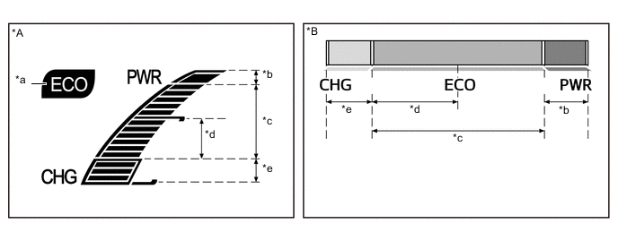
Text in Illustration *A Models without Multi-information Display *B Models with Multi-information Display *a Eco Driving Indicator Light *b Power Area *c Eco Area *d Eco Area (Hybrid Eco Area) *e Charge Area - -
-
-
Headup Display
-
The headup display on which vehicle information and system control information are displayed is provided. The following information items are displayed.
Display Outline Vehicle Speed The vehicle speed is displayed. Turn-by-turn Navigation* Turn-by-turn navigation information is displayed based on the signal from the navigation system. Warning Display A warning issued by dynamic radar cruise control, pre-crash safety system or lane departure alert system is displayed. *: Models with navigation system
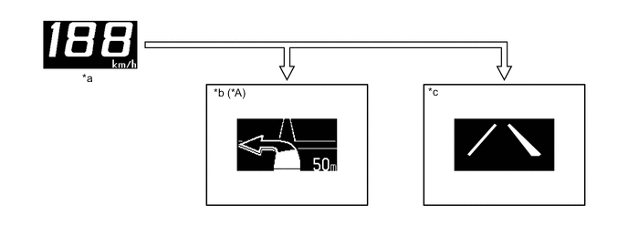
Text in Illustration *A Models with Navigation System - - *a Vehicle Speed Display *b Advisory Display *c Warning Display - - 
Displayed when the necessary conditions are met. - -
-
-
-
PRECAUTION
-
Headup Display
-
The headup display may seem dark and hard to see when viewed through sunglasses, especially polarized sunglasses.
-
-