CYLINDER HEAD REPLACEMENT
-
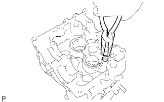
REMOVE VALVE STEM OIL SEAL
-
Using needle-nose pliers, remove the oil seal.
-
-
REMOVE INTAKE VALVE GUIDE BUSH
-
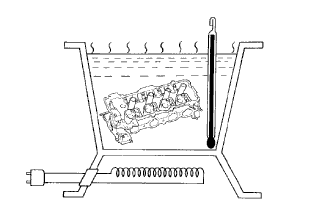
Gradually heat the cylinder head to approximately 80 to 100°C (176 to 212°F).
-
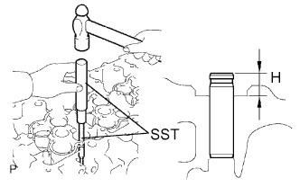
Using SST and a hammer, tap out the valve guide bush.
- SST
- 09201-10000 ( 09201-01060 )
- 09950-70010 ( 09951-07100 )
-
-
REMOVE EXHAUST VALVE GUIDE BUSH
-
Gradually heat the cylinder head to approximately 80 to 100°C (176 to 212°F).
-
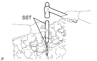
Using SST and a hammer, tap out the valve guide bush.
- SST
- 09201-10000 ( 09201-01060 )
- 09950-70010 ( 09951-07100 )
-
-
INSTALL INTAKE VALVE GUIDE BUSH
-
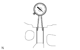
Using a caliper gauge, measure the bush bore diameter of the cylinder head.
Select a new guide bush (STD or O/S 0.05) Bush Size Bush Bore Diameter Use STD 10.985 to 11.006 mm (0.4325 to 0.4333 in.) Use O/S 0.05 11.035 to 11.056 mm (0.4344 to 0.4353 in.) If the bush bore diameter of the cylinder head is greater than 11.006 mm (0.4333 in.), machine the bush bore diameter to between 11.035 to 11.056 mm (0.4344 to 0.4353 in.).
If the bush bore diameter of the cylinder head is greater than 11.056 mm (0.4353 in.), replace the cylinder head.
-
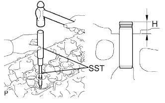
Gradually heat the cylinder head to approximately 80 to 100°C (176 to 212°F).
-
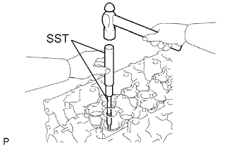
Using SST and a hammer, tap in a new guide bush to the specified protrusion height.
- SST
- 09201-10000 ( 09201-01060 )
- 09950-70010 ( 09951-07100 )
Standard protrusion height (H) 10.3 to 10.7 mm (0.406 to 0.421 in.) -
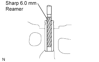
Using a sharp 6.0 mm reamer, ream the guide bush to obtain the standard specified clearance between the guide bush and valve stem.
-
-
INSTALL EXHAUST VALVE GUIDE BUSH
-
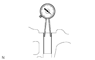
Using a caliper gauge, measure the bush bore diameter of the cylinder head.
Select a new guide bush (STD or O/S 0.05) Bush Size Bush Bore Diameter Use STD 10.985 to 11.006 mm (0.4325 to 0.4333 in.) Use O/S 0.05 11.035 to 11.056 mm (0.4344 to 0.4353 in.) If the bush bore diameter of the cylinder head is greater than 11.006 mm (0.4333 in.), machine the bush bore diameter to between 11.035 to 11.056 mm (0.4344 to 0.4353 in.).
If the bush bore diameter of the cylinder head is greater than 11.056 mm (0.4353 in.), replace the cylinder head.
-
Gradually heat the cylinder head to approximately 80 to 100°C (176 to 212°F).
-
Using SST and a hammer, tap in a new guide bush to the specified protrusion height.
- SST
- 09201-10000 ( 09201-01060 )
- 09950-70010 ( 09951-07100 )
Standard protrusion height (H) 10.3 to 10.7 mm (0.406 to 0.421 in.) -
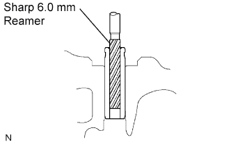
Using a sharp 6.0 mm reamer, ream the guide bush to obtain the standard specified clearance between the guide bush and valve stem.
-
-
INSTALL VALVE STEM OIL SEAL
-
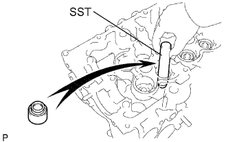
Using SST, push in a new oil seal.
- SST
- 09201-41020
-
-
INSTALL CAMSHAFT OIL SEAL
-
Apply MP grease to the lip of a new oil seal.
-
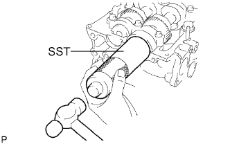
Using SST and a hammer, tap in the oil seal until its surface is flush with the oil seal retainer edge.
- SST
- 09608-06041
-