AUTOMATIC TRANSAXLE SYSTEM
-
CONSTRUCTION
-
The 8-speed configuration has been achieved by using 2 planetary gear units, creating an 8-speed automatic transaxle.
-
A Ravigneaux type planetary gear unit is used as the rear planetary gear unit. The gear unit consists of pairs of sun gears (middle and rear) and planetary pinion gears (long and short) with different diameters within a single planetary gear.
-
A centrifugal fluid pressure canceling mechanism is used in the C1, C2, C3 and C4 clutches that are applied when shifting between 1st to 8th gears.
-
The shapes of the grooves in the clutches and brake linings have been optimized in order to reduce drag.
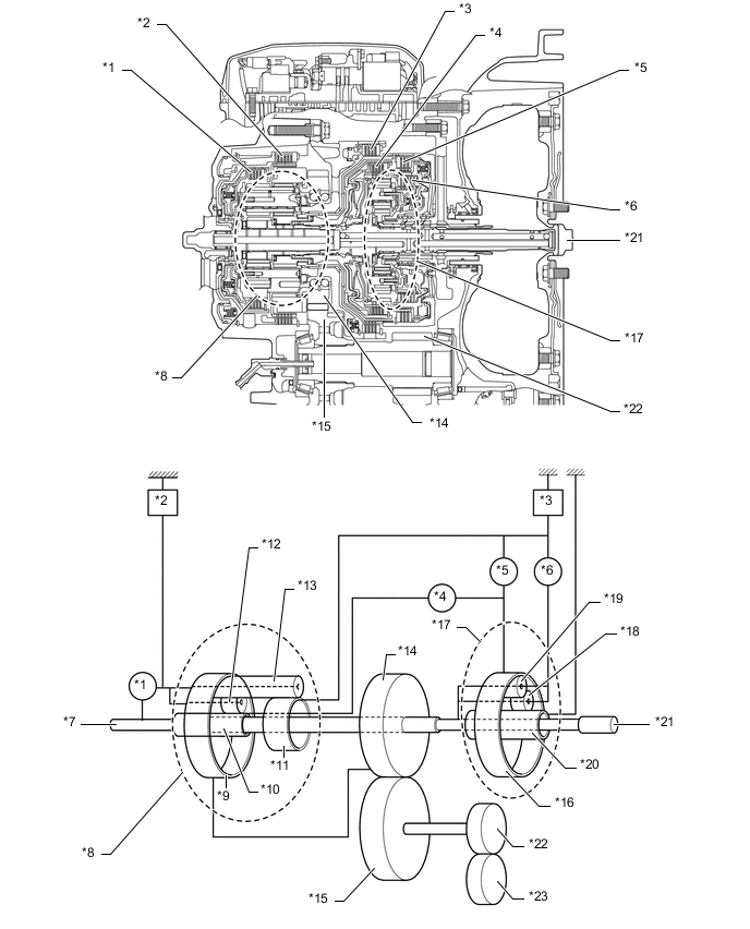
*1 C2 Clutch *2 B2 Brake *3 B1 Brake *4 C1 Clutch *5 C3 Clutch *6 C4 Clutch *7 Intermediate Shaft *8 Rear Planetary Gear Unit *9 Rear Planetary Ring Gear *10 Rear Sun Gear *11 Middle Sun Gear *12 Short Pinion *13 Long Pinion *14 Counter Drive Gear *15 Counter Driven Gear *16 Front Planetary Ring Gear *17 Front Planetary Gear Unit *18 Inner Pinion *19 Outer Pinion *20 Front Sun Gear *21 Input Shaft *22 Differential Drive Pinion *23 Differential Ring Gear - - -
The functions of the clutches and brakes are as follows
Component Function C1 No. 1 Clutch Connects front planetary ring gear and rear sun gear. C2 No. 2 Clutch Connects intermediate shaft and rear planetary carrier. C3 No. 3 Clutch Connects front planetary ring gear and middle sun gear. C4 No. 4 Clutch Connects front planetary carrier and middle sun gear. B1 No. 1 Brake Prevents middle sun gear from turning either clockwise or counterclockwise. B2 No. 2 Brake Prevents rear planetary carrier from turning either clockwise or counterclockwise. Planetary Gears These gears change the route through which driving force is transmitted, in accordance with the operation of each clutch and brake, in order to increase or reduce the input and output speeds. -
A tolerance ring is used to increase the lock-up range and increase fuel economy due to the reduced spline tooth clearance.
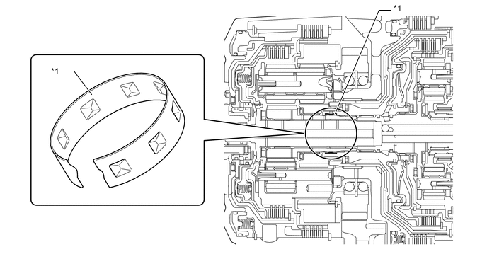
*1 Tolerance Ring - -
-
-
OPERATION
-
Transaxle Power Flow
Operating Condition of Shift Solenoid Valves Shift Position, Shift Range and Gear Range Shift Solenoid Valve SL1 SL2 SL3 SL4 SL5 SL6 SL SLU P - - - - - - ○ - R - - ○ - - ○ ○ - N*1 - - - - - ▲ ○ - N*2 - - - - - - ○ - D 1st ○ - - - - ○ ● ● 2nd ○ - - - ○ - ● ● 3rd ○ - ○ - - - ● ● 4th ○ - - ○ - - ● ● 5th ○ ○ - - - - ● ● 6th - ○ - ○ - - ● ● 7th - ○ ○ - - - ● ● 8th - ○ - - ○ - ● ● S S1 ○ - - - - ○ ● ● S2 ○ - - - ○ - ● ● S3 ○ - ○ - - - ● ● S4 ○ - - ○ - - ● ● S5 ○ ○ - - - - ● ● S6 - ○ - ○ - - ● ● S7 - ○ ○ - - - ● ● S8 - ○ - - ○ - ● ● ○: ON (Applied)
-: OFF (Release)
▲: Controlled
●: Lock-up ON/OFF
*1: Vehicle speed is 11 km/h (6.8 mph) or less.
*2: Vehicle speed is below 11 km/h (6.8 mph).
Operating Condition of Friction Engagement Components Shift Position, Shift Range and Gear Range Clutch Brake C1 C2 C3 C4 B1 B2 P - - - - - - R - - ○ - - ○ N*1 - - - - - ▲ N*2 - - - - - - D 1st ○ - - - - ○ 2nd ○ - - - ○ - 3rd ○ - ○ - - - 4th ○ - - ○ - - 5th ○ ○ - - - - 6th - ○ - ○ - - 7th - ○ ○ - - - 8th - ○ - - ○ - S S1 ○ - - - - ○ S2 ○ - - - ○ - S3 ○ - ○ - - - S4 ○ - - ○ - - S5 ○ ○ - - - - S6 - ○ - ○ - - S7 - ○ ○ - - - S8 - ○ - - ○ - ○: ON (Applied)
-: OFF (Release)
▲: Controlled
*1: Vehicle speed is 11 km/h (6.8 mph) or less.
*2: Vehicle speed is below 11 km/h (6.8 mph).
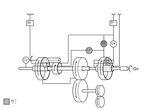
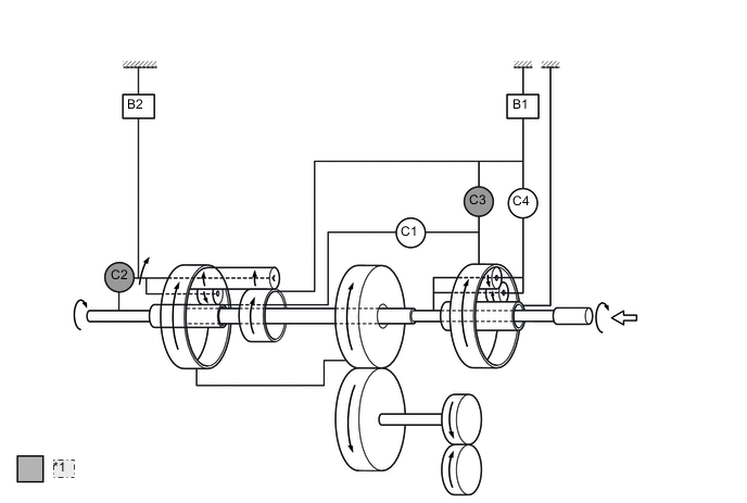
Figure 1. 1st Gear
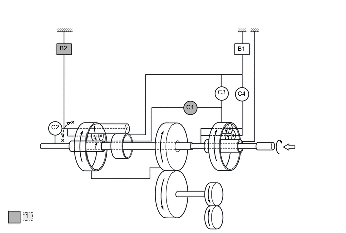
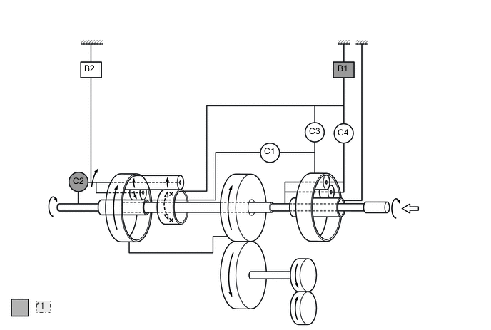
*1 Operates Figure 2. 2nd Gear
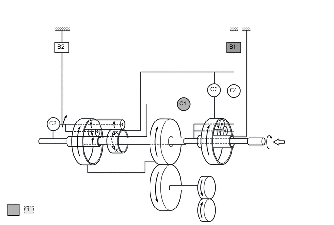
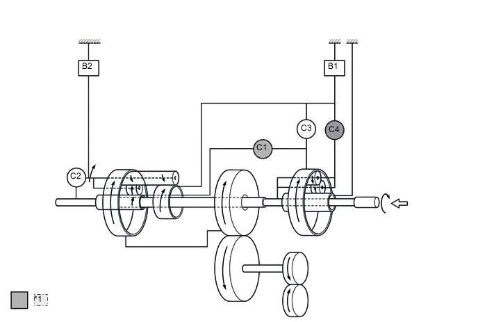
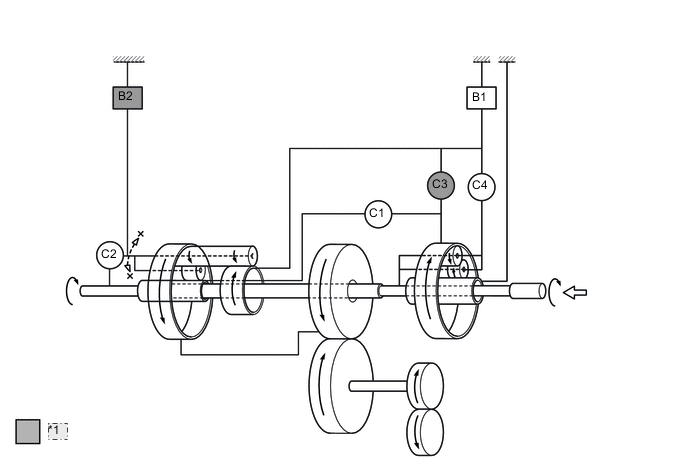
*1 Operates Figure 3. 3rd Gear
*1 Operates Figure 4. 4th Gear
*1 Operates Figure 5. 5th Gear
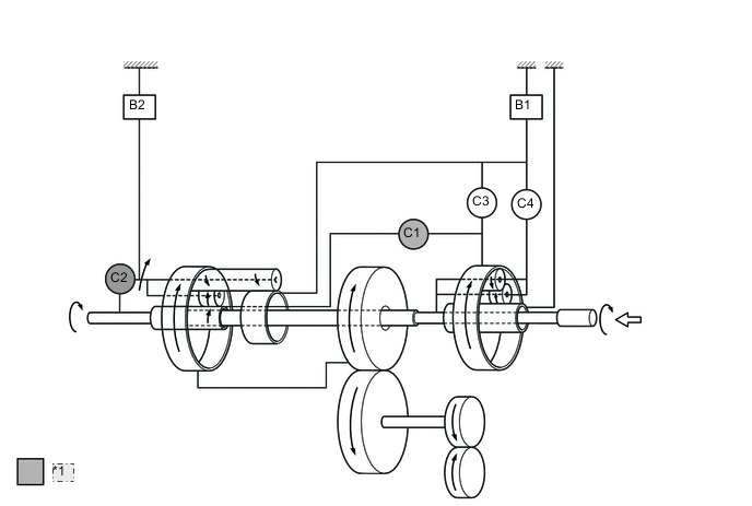
*1 Operates Figure 6. 6th Gear
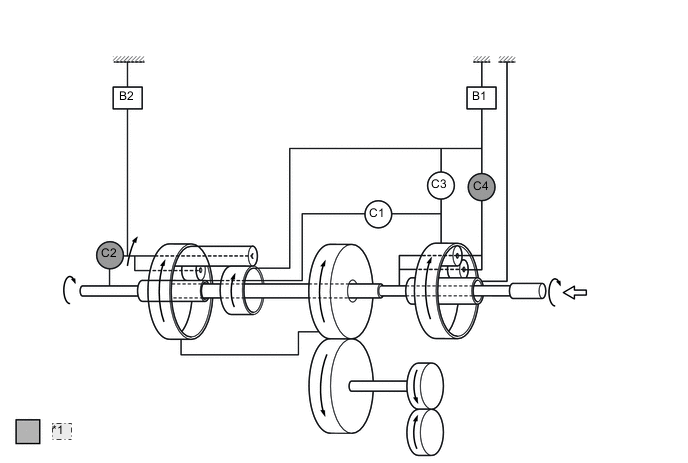
*1 Operates Figure 7. 7th Gear
*1 Operates Figure 8. 8th Gear
*1 Operates Figure 9. Reverse Gear
*1 Operates
-