AIR CONDITIONING SYSTEM(for Automatic Air Conditioning System), Diagnostic DTC:B130D
| DTC Code | DTC Name |
|---|---|
| B130D | Recirculation Motor Fault |
DESCRIPTION
The No. 1 damper servo sub-assembly sends pulse signals to inform the air conditioning control assembly of the damper position. The air conditioning control assembly activates the motor (normal or reverse) based on these signals to move the air inlet mode selection No. 1 damper servo sub-assembly to the appropriate position, which controls the air inlet mode (fresh, recirculation/fresh, and recirculation).
DTC No. |
Detection Item |
DTC Detection Condition |
Trouble Area |
|---|---|---|---|
B130D |
Recirculation Motor Fault |
Air inlet damper position sensor value does not change even if air conditioning control assembly operates No. 1 damper servo sub-assembly |
|
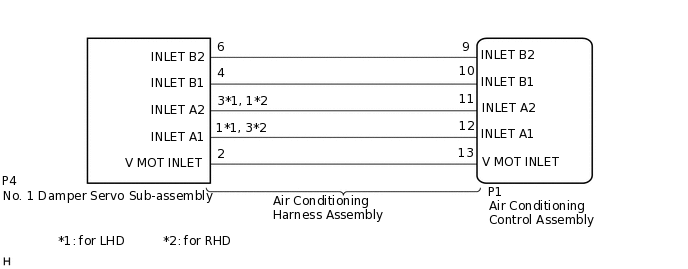
WIRING DIAGRAM
PROCEDURE
CHECK AIR CONDITIONING HARNESS ASSEMBLY (AIR CONDITIONING CONTROL ASSEMBLY - NO. 1 DAMPER SERVO SUB-ASSEMBLY)
Disconnect the P1 air conditioning control assembly connector.
Disconnect the P4 No. 1 damper servo sub-assembly connector.
Measure the resistance according to the value(s) in the table below.
Standard Resistance
Table 1. for LHD Tester Connection
Condition
Specified Condition
P1-9 (INLET B2) - P4-6 (INLET B2)
Always
Below 1 Ω
P1-10 (INLET B1) - P4-4 (INLET B1)
Always
Below 1 Ω
P1-11 (INLET A2) - P4-3 (INLET A2)
Always
Below 1 Ω
P1-12 (INLET A1) - P4-1 (INLET A1)
Always
Below 1 Ω
P1-13 (V MOT INLET) - P4-2 (V MOT INLET)
Always
Below 1 Ω
P1-9 (INLET B2) - Body ground
Always
10 kΩ or higher
P1-10 (INLET B1) - Body ground
Always
10 kΩ or higher
P1-11 (INLET A2) - Body ground
Always
10 kΩ or higher
P1-12 (INLET A1) - Body ground
Always
10 kΩ or higher
P1-13 (V MOT INLET) - Body ground
Always
10 kΩ or higher
Table 2. for RHD Tester Connection
Condition
Specified Condition
P1-9 (INLET B2) - P4-6 (INLET B2)
Always
Below 1 Ω
P1-10 (INLET B1) - P4-4 (INLET B1)
Always
Below 1 Ω
P1-11 (INLET A2) - P4-1 (INLET A2)
Always
Below 1 Ω
P1-12 (INLET A1) - P4-3 (INLET A1)
Always
Below 1 Ω
P1-13 (V MOT INLET) - P4-2 (V MOT INLET)
Always
Below 1 Ω
P1-9 (INLET B2) - Body ground
Always
10 kΩ or higher
P1-10 (INLET B1) - Body ground
Always
10 kΩ or higher
P1-11 (INLET A2) - Body ground
Always
10 kΩ or higher
P1-12 (INLET A1) - Body ground
Always
10 kΩ or higher
P1-13 (V MOT INLET) - Body ground
Always
10 kΩ or higher
Result
Proceed to
OK
NG
REPLACE NO. 1 DAMPER SERVO SUB-ASSEMBLY
Replace the No. 1 damper servo sub-assembly.
Tip:Since the servo motor cannot be inspected while it is removed from the vehicle, replace the servo motor with a new or known good one and check that the condition returns to normal.
When troubleshooting according to the DTC.
Check for DTCs.
Body Electrical > Air Conditioner > Trouble Codes
When troubleshooting according to Problem Symptoms Table.
OK
Malfunction disappears.
Result
Result
Proceed to
DTC B130D is output (When troubleshooting according to the DTC)
A
NG (When troubleshooting according to Problem Symptoms Table)
B
DTC B130D is not output (When troubleshooting according to the DTC)
C
OK (When troubleshooting according to Problem Symptoms Table)
C END (NO. 1 DAMPER SERVO SUB-ASSEMBLY WAS DEFECTIVE)