ENGINE UNIT
-
CONSTRUCTION
-
An aluminum cylinder block sub-assembly is used to achieve a lightweight design.
-
The liners are a spiny-type, which have been manufactured so that their casting exteriors form large irregular surfaces in order to enhance the adhesion between the liners and the aluminum cylinder block sub-assembly. The enhanced adhesion helps heat dissipation, resulting in a lower overall temperature and reduced heat deformation of the cylinder bores.
-
The front side water jacket of the No. 1 cylinder has been eliminated and the longitudinal distance between head bolts for the No. 1 cylinder has been reduced, resulting in a shorter engine length and compact design.
-
By positioning the water jackets adjacent to the oil drain paths, heat transfer between them has been enhanced. With this, cold engine warm-up capability is enhanced and excessive oil temperatures are reduced when the engine load is high, ensuring vehicle reliability.
-
Cooling passages are drilled between each cylinder bore to provide increased cooling to the upper part of the cylinder bore which is most susceptible to heat. This minimizes deformation of the cylinder bore, ensuring high power output and reduced oil consumption.
-
A larger breather hole is provided in the No. 1 to No. 4 journal wall. As a result, friction is reduced and output performance is improved.
-
The angle of the bore cross hatching, the polishing on the cylinder liner surface, is at an angle of 30°, thus improving the oil retention of the interior of the cylinder bore. This reduces the friction between the cylinder bore and the piston, improving fuel consumption.
-
The shape of the ribs, and the positioning and shape of the knock control sensor have been optimized, thus improving control of knocking.
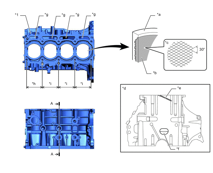
*1 Cylinder Block Sub-assembly - - *a Cylinder Bore *b Spiny-type Liner (Irregularly Shaped Outer Casting Surface of Liner) *c Bore Cross Hatch *d A-A Cross Section *e Water Passage *f Larger Breather Hole *g Oil Drain Passage *h 94 mm (3.70 in.) *i 97 mm (3.82 in.) - - -
Through the use of an offset crankshaft, the centerline of the bores is shifted 10 mm (0.394 in.) towards the intake side in relation to the centerline of the crankshaft. Thus, the side force to the cylinder wall is reduced when the maximum pressure is applied. This contributes to fuel economy.
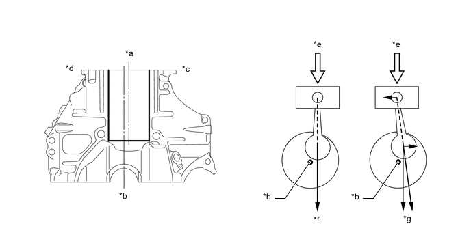
*a Bore Centerline *b Crankshaft Center *c Intake Side *d Exhaust Side *e Maximum Pressure *f Offset Crankshaft *g Non-offset Crankshaft - - -
A precision molded resin cylinder block water jacket spacer with excellent heat resistance is used inside the water jacket of the cylinder block sub-assembly. The cylinder block water jacket spacers optimize the flow of coolant within the water jackets, keeping the temperature of the cylinder bore walls uniform to suppress engine knock.
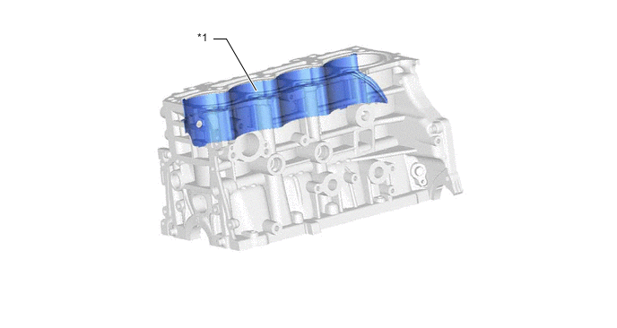
*1 Cylinder Block Water Jacket Spacer - -
-