AUTOMATIC TRANSMISSION UNIT (for 1KD-FTV) DISASSEMBLY

-
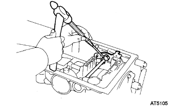
REMOVE TRANSMISSION CONTROL SHAFT LEVER LH
-
Remove the nut, the washer and the transmission control shaft lever LH.
-
-
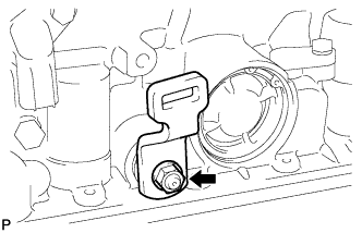
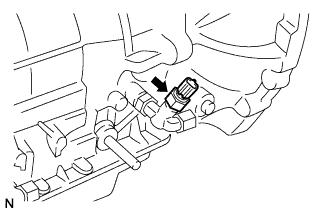
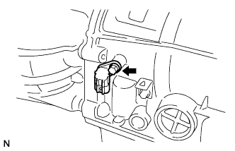
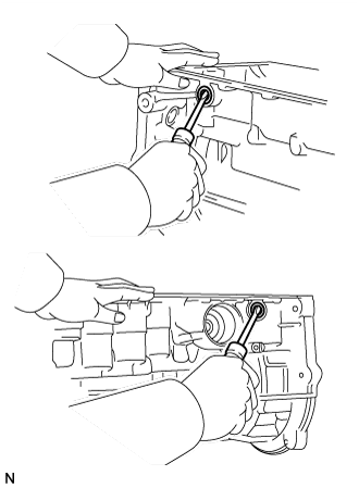
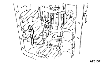
REMOVE PARK/NEUTRAL POSITION SWITCH ASSEMBLY
-
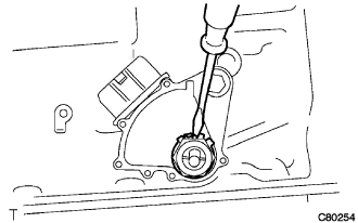
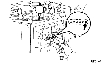
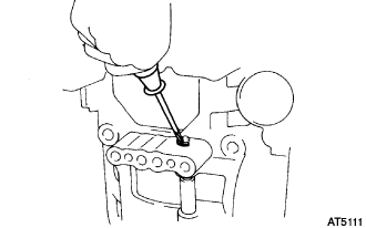
Using a screwdriver, unstake the lock washer.
-
Remove the nut and the lock washer.
-
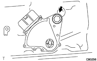
Remove the bolt and the park/neutral position switch assembly.
Tech Tips
Make sure that the manual valve lever shaft has not been rotated prior to installing the park/neutral position switch as the detent spring may become detached from the manual valve lever shaft.
-
-
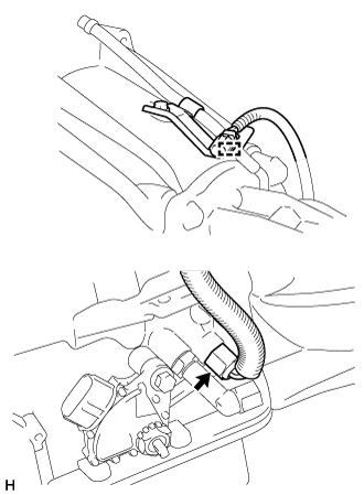
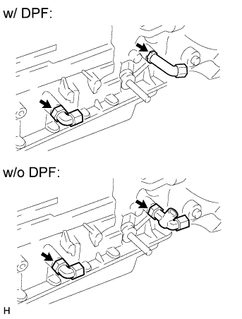
REMOVE TEMPERATURE SENSOR (w/ DPF)
-
Detach the temperature sensor connector clamp from the wire harness bracket.
-
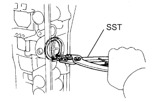
Using a 19 mm union nut wrench, remove the temperature sensor from the automatic transmission assembly.
-
Remove the O-ring from the temperature sensor.
-
-
REMOVE TEMPERATURE SENSOR (w/o DPF)
-
Remove the temperature sensor.
-
Remove the O-ring from the temperature sensor.
-
-
REMOVE OIL COOLER TUBE UNION
-
Remove the 2 oil cooler tube unions.
-
Remove the O-rings from each oil cooler tube union.
-
-
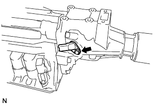
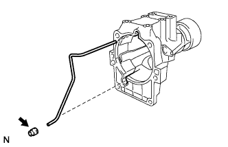
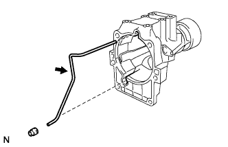
REMOVE BREATHER HOSE
-
Remove the bolt and breather plug hose from the automatic transmission housing.
-
-
REMOVE SPEEDOMETER SENSOR (w/ Speedometer Sensor)
-
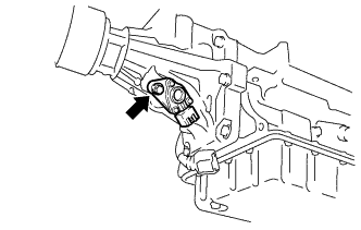
Remove the bolt and the speedometer sensor.
-
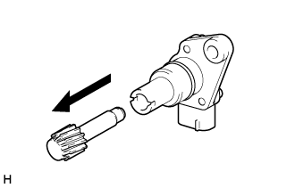
Remove the speedometer driven gear from the speedometer sensor.
-
Remove the O-ring from the speedometer sensor.
-
-
REMOVE SPEED SENSOR NC0
-
Remove the bolt and the speed sensor NC0.
-
Remove the O-ring from the speed sensor NC0.
-
-
REMOVE SPEED SENSOR SP2
-
Remove the bolt and the speed sensor SP2.
-
Remove the O-ring from the speed sensor SP2.
-
-
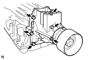
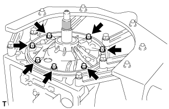
REMOVE AUTOMATIC TRANSMISSION HOUSING
-
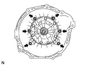
Remove the 6 bolts.
-
Remove the automatic transmission housing.
-
-
FIX AUTOMATIC TRANSMISSION CASE SUB-ASSEMBLY
-
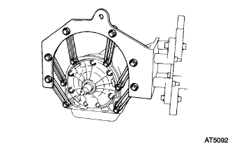
Install the automatic transmission case sub-assembly onto the overhaul attachment.
-
-
REMOVE EXTENSION HOUSING SUB-ASSEMBLY
-
Remove the 6 bolts.
-
Remove the extension housing sub-assembly and the extension housing gasket.
-
-
REMOVE EXTENSION HOUSING BUSH APPLY TUBE GASKET
-
Remove the extension housing bush apply tube gasket.
-
-
REMOVE EXTENSION HOUSING BUSH APPLY TUBE
-
Remove the extension housing bush apply tube.
-
-
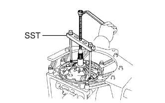
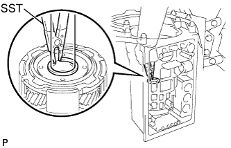
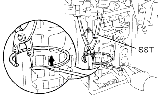
REMOVE AUTOMATIC TRANSMISSION EXTENSION HOUSING OIL SEAL
-
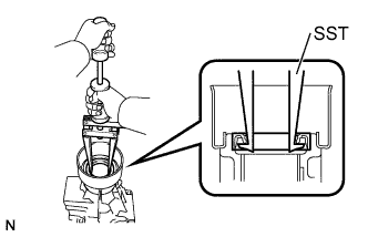
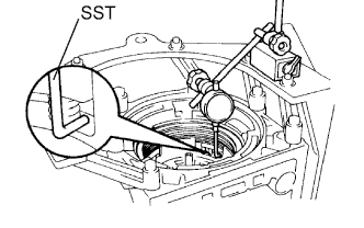
Using SST, remove the automatic transmission extension housing oil seal.
- SST
- 09308-00010
-
-
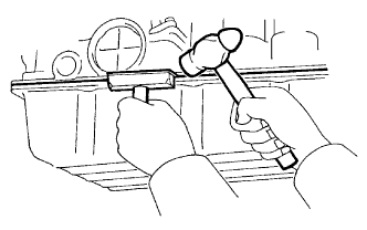
REMOVE EXTENSION HOUSING DUST DEFLECTOR
-
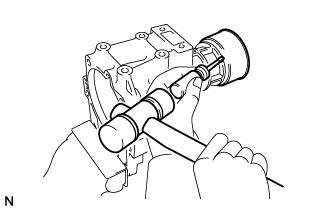
Mount the extension housing sub-assembly in a soft jaw vise.
-
Using a screwdriver and a hammer, remove the extension housing dust deflector.
-
-
INSPECT EXTENSION HOUSING SUB-ASSEMBLY
-
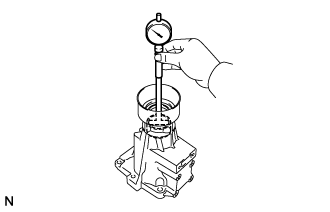
Using a cylinder gauge, measure the inside diameter of the extension housing bushing.
Maximum inside diameter 40.03 mm (1.5760 in.) If the inside diameter is greater than the maximum, replace the extension housing.
-
-
REMOVE SPEEDOMETER DRIVE GEAR (w/ Speedometer Sensor)
-
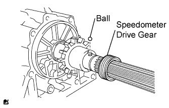
Using snap ring expander, remove the snap ring.
-
Remove the speedometer drive gear and the ball.
-
-
REMOVE SENSOR ROTOR (w/ Speedometer Sensor)
-
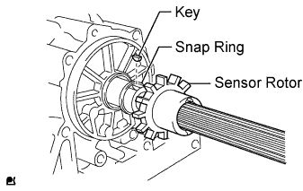
Remove the sensor rotor and the key.
-
Using snap ring expander, remove the snap ring.
-
-
REMOVE SENSOR ROTOR (w/o Speedometer Sensor)
-
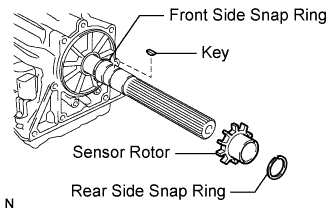
Using snap ring expander, remove the rear side snap ring.
-
Remove the sensor rotor and the key.
-
Using snap ring expander, remove the front side snap ring.
-
-
REMOVE AUTOMATIC TRANSMISSION OIL PAN SUB-ASSEMBLY
-
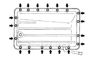
Remove the 19 bolts.
Note
Do not turn the transmission over as this will contaminate the valve body with any foreign matter at the bottom of the automatic transmission oil pan sub-assembly.
-
Insert the blade of an oil pan seal cutter between the transmission case and automatic transmission oil pan sub-assembly, and then cut through the applied sealer.
Note
Be careful not to damage the flanges of the automatic transmission oil pan sub-assembly and transmission case.
-
Remove the automatic transmission oil pan sub-assembly by lifting the transmission case.
-
-
INSPECT AUTOMATIC TRANSMISSION OIL PAN SUB-ASSEMBLY
-
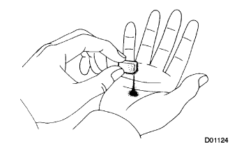
Remove the oil cleaner magnets, and use them to collect steel particles.
Carefully look at the foreign matter and particles in the pan and on the oil cleaner magnets to anticipate the type of wear you will find in the transmission.
Steel (magnetic) Bearing, gear and clutch plate wear Brass (non-magnetic) Bushing wear
-
-
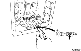
REMOVE VALVE BODY OIL STRAINER ASSEMBLY
-
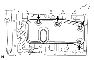
Remove the 4 bolts.
-
Remove the valve body oil strainer assembly and the 5 gaskets.
-
-
REMOVE TRANSMISSION WIRE
-
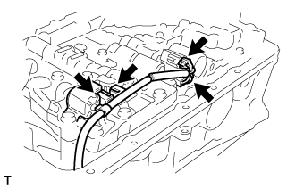
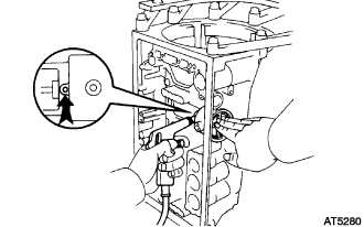
Disconnect the 4 connectors from each shift solenoid valve.
-
Remove the bolt.
-
Pull out the transmission wire from the automatic transmission case sub-assembly.
-
Remove the O-ring from the transmission wire.
-
-
REMOVE TRANSMISSION VALVE BODY ASSEMBLY
-
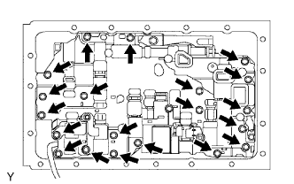
Remove the 20 bolts and the transmission valve body assembly.
-
-
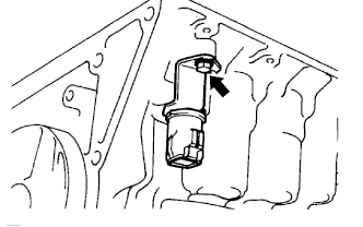
REMOVE CHECK BALL BODY
-
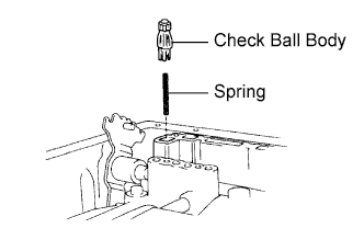
Remove the check ball body and the spring.
-
-
REMOVE B-2 ACCUMULATOR PISTON
-
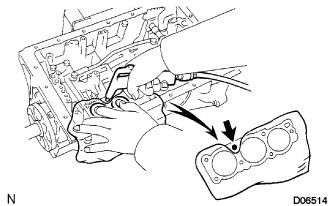
Applying compressed air (392 kPa, 4.0 kgf/cm2, 57 psi) to the oil hole, remove the B-2 accumulator piston and the spring.
Note
-
The application of compressed air may cause the piston to jump out. When removing the piston, hold it using a shop rag or piece of cloth.
-
Take care not to splash ATF when applying the compressed air.
-
-
Remove the 2 O-rings from the B-2 accumulator piston.
-
-
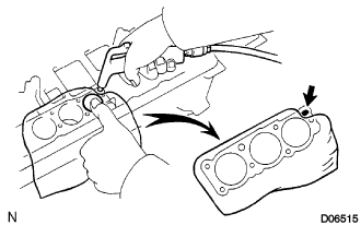
REMOVE C-2 ACCUMULATOR PISTON
-
Applying compressed air (392 kPa, 4.0 kgf/cm2, 57 psi) to the oil hole, remove the C-2 accumulator piston and the 2 springs.
Note
-
The application of compressed air may cause the piston to jump out. When removing the piston, hold it using a shop rag or piece of cloth.
-
Take care not to splash ATF when applying the compressed air.
-
-
Remove the 2 O-rings from the C-2 accumulator piston.
-
-
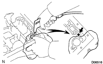
REMOVE B-0 ACCUMULATOR PISTON
-
Applying compressed air (392 kPa, 4.0 kgf/cm2, 57 psi) to the oil hole, remove the B-0 accumulator piston and the spring.
Note
-
The application of compressed air may cause the piston to jump out. When removing the piston, hold it using a shop rag or piece of cloth.
-
Take care not to splash ATF when applying compressed air.
-
-
Remove the 2 O-rings from the B-0 accumulator piston.
-
-
REMOVE C-0 ACCUMULATOR PISTON
-
Applying compressed air (392 kPa, 4.0 kgf/cm2, 57 psi) to the oil hole, remove the C-0 accumulator piston and the 2 springs.
Note
-
The application of compressed air may cause the piston to jump out. When removing the piston, hold it using a shop rag or piece of cloth.
-
Take care not to splash ATF when applying compressed air.
-
-
Remove the O-ring from the C-0 accumulator piston.
-
-
REMOVE PARKING LOCK PAWL BRACKET
-
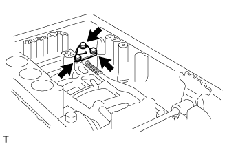
Remove the 3 bolts and the parking lock pawl bracket.
-
-
REMOVE PARKING LOCK ROD SUB-ASSEMBLY
-
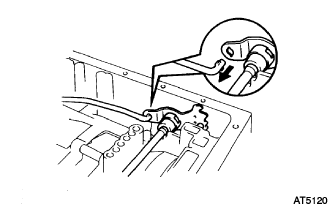
Disconnect the parking lock rod sub-assembly from the manual valve lever sub-assembly.
-
-
REMOVE PARKING LOCK PAWL SHAFT
-
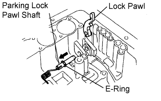
Pull out the parking lock pawl shaft from the front side, then remove the lock pawl and the spring.
-
Remove the E-ring from the parking lock pawl shaft.
-
-
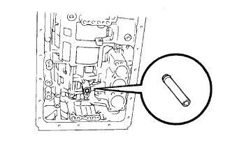
REMOVE MANUAL VALVE LEVER SUB-ASSEMBLY
-
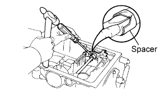
Using a hammer and screwdriver, cut off the spacer and remove it from the manual valve lever shaft sub-assembly.
-
Using a pin punch and hammer, drive out the pin.
Tech Tips
Slowly drive out the pin so that it does not fall into the transmission case.
-
Pull out the manual valve lever shaft through the automatic transmission case sub-assembly, and remove the manual valve lever sub-assembly.
-
-
REMOVE MANUAL VALVE LEVER SHAFT OIL SEAL
-
Using a screwdriver, remove the 2 manual valve lever shaft oil seals.
-
-
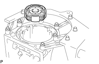
REMOVE FRONT OIL PUMP BODY SUB-ASSEMBLY
-
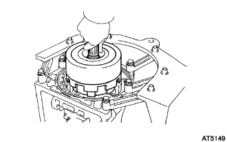
Stand up the transmission.
-
Remove the 7 bolts.
-
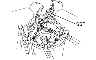
Using SST, remove the front oil pump body sub-assembly.
- SST
- 09350-30020 ( 09350-07020 )
-
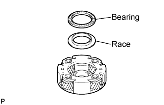
Remove the O-ring from the front oil pump body sub-assembly.
-
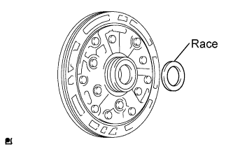
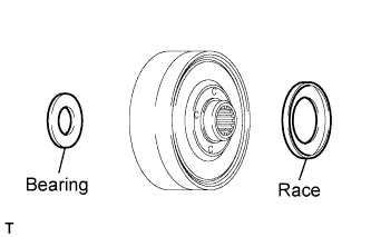
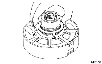
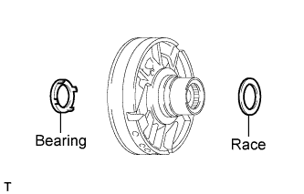
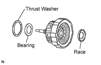
Remove the thrust bearing race from the front oil pump body sub-assembly.
-
-
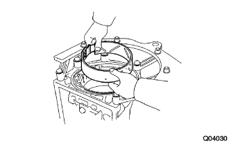
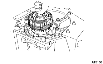
REMOVE OVERDRIVE PLANETARY GEAR ASSEMBLY
-
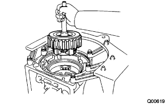
Remove the overdrive planetary gear, overdrive direct clutch and one-way clutch from the automatic transmission case sub-assembly.
-
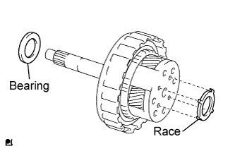
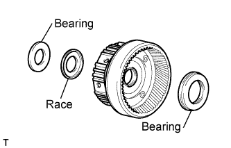
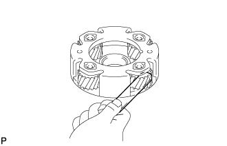
Remove the thrust needle roller bearing and the thrust bearing race from overdrive planetary gear assembly.
-
-
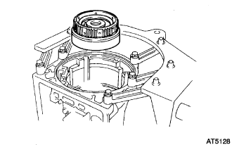
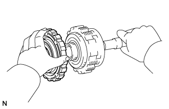
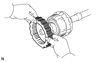
REMOVE OVERDRIVE PLANETARY RING GEAR
-
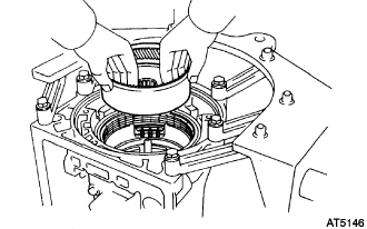
Remove the overdrive planetary ring gear from the automatic transmission case sub-assembly.
-
Remove the thrust needle roller bearing and the thrust bearing race from the overdrive planetary ring gear.
-
-
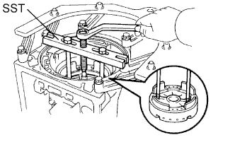
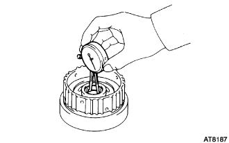
INSPECT OVERDRIVE BRAKE PISTON
-
Place SST and a dial indicator onto the overdrive brake piston.
- SST
- 09350-30020 ( 09350-06120 )
-
Measure the stroke while applying and releasing compressed air (392 kPa, 4.0 kgf/cm2, 57 psi).
Piston stroke 1.40 to 1.70 mm (0.0551 to 0.0669 in.) If the piston stroke is less than the limit, parts may be assembled incorrectly, so check and reassemble them if necessary.
If the piston stroke is still outside the specified range, select another flange.
Tech Tips
There are 7 different thicknesses for the flange.
Flange thickness No. Thickness No. Thickness 77 3.3 mm (0.130 in.) 81 3.8 mm (0.150 in.) 78 3.5 mm (0.138 in.) 82 3.9 mm (0.154 in.) 79 3.6 mm (0.142 in.) 83 4.0 mm (0.157 in.) 80 3.7 mm (0.146 in.) - -
-
-
REMOVE OVERDRIVE BRAKE PACK
-
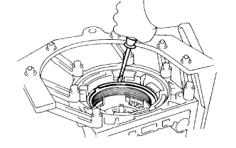
Using a screwdriver, remove the snap ring.
Tech Tips
Tape up the screwdriver tip before use.
-
Remove the overdrive brake pack.
-
-
INSPECT PISTON STROKE OF 2ND COAST BRAKE
-
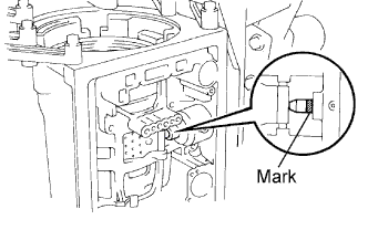
Place a mark on the 2nd coast brake piston rod.
-
Using SST, measure the stroke while applying and releasing compressed air (392 kPa, 4.0 kgf/cm2, 57 psi).
- SST
- 09240-00020
Piston rod stroke 1.50 to 3.00 mm (0.0591 to 0.1181 in.) If the stroke is outside the specified range, replace the piston rod.
Piston rod length 78.4 mm (3.087 in.) or 79.9 mm (3.146 in.) If the stroke is still outside the specified range, replace the 2nd coast brake band assembly with a new one.
-
-
INSPECT OUTPUT SHAFT
-
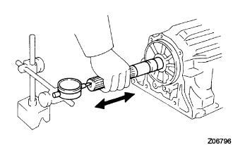
Using a dial indicator, measure the end play of the output shaft by hand.
End play 0.30 to 1.04 mm (0.0118 to 0.0409 in.) If the value is outside the standard range, check for improper installation.
-
Check that the output shaft rotates smoothly.
-
-
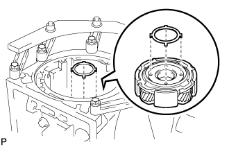
REMOVE OVERDRIVE SUPPORT SUB-ASSEMBLY
-
Remove the 2 bolts from the automatic transmission case sub-assembly.
-
Using SST, remove the snap ring.
- SST
- 09350-30020 ( 09350-07020, 09350-07060 )
-
Using SST, remove the overdrive support sub-assembly.
- SST
- 09350-30020 ( 09350-07020 )
-
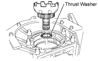
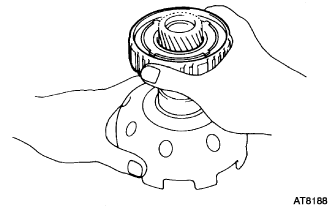
Remove the clutch drum thrust washer from the overdrive support sub-assembly.
-
Remove the thrust needle roller bearing and the thrust bearing race from the overdrive support sub-assembly.
-
-
REMOVE 2ND COAST BRAKE PISTON
-
Using SST, remove the snap ring.
- SST
- 09350-30020 ( 09350-07060 )
-
Applying compressed air (392 kPa, 4.0 kgf/cm2, 57 psi) to the oil hole, remove the 2nd coast brake cover, the 2nd coast brake piston and the spring.
-
Remove the 2 O-rings from the 2nd coast brake cover.
-
-
REMOVE DIRECT CLUTCH ASSEMBLY
-
Remove the direct clutch assembly with the forward clutch assembly from the automatic transmission case sub-assembly.
-
-
REMOVE FORWARD CLUTCH ASSEMBLY
-
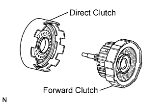
Remove the forward clutch assembly from the direct clutch assembly.
-
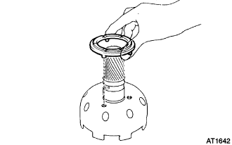
Remove the No. 2 clutch drum thrust washer, thrust needle roller bearing and thrust bearing race from the forward clutch assembly.
-
-
REMOVE 2ND COAST BRAKE BAND ASSEMBLY
-
Using a screwdriver, remove the E-ring from the pin.
Tech Tips
Apply grease to the E-ring and the pin before the work so that the ring does not fly out.
-
Remove the pin from the 2nd coast brake band assembly.
-
Remove the E-ring from the pin.
-
Remove the 2nd coast brake band assembly from the automatic transmission case sub-assembly.
-
-
REMOVE FRONT PLANETARY RING GEAR SUB-ASSEMBLY
-
Remove the front planetary ring gear sub-assembly from the automatic transmission case sub-assembly.
-
Remove the 2 thrust needle roller bearings and the thrust bearing race from the front planetary ring gear sub-assembly.
-
Remove the thrust bearing race from the front planetary gear assembly.
-
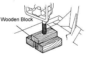
With wooden blocks or equivalent placed under the output shaft, stand the transmission on the output shaft.
-
-
INSPECT FRONT PLANETARY RING GEAR SUB-ASSEMBLY
-
Using a dial indicator, measure the inside diameter of the planetary ring gear bushing.
Maximum inside diameter 24.02 mm (0.9457 in.) If the inside diameter is greater than the maximum, replace the planetary ring gear sub-assembly.
-
-
REMOVE FRONT PLANETARY GEAR ASSEMBLY
-
Using SST, remove the snap ring.
- SST
- 09350-30020 ( 09350-07070 )
Tech Tips
Pushing the output shaft towards the front makes it easier to remove the snap ring.
-
Remove the front planetary gear assembly from the automatic transmission case sub-assembly.
-
Remove the thrust needle roller bearing and the thrust bearing race from the front planetary gear assembly.
If necessary, using a screw driver.
-
-
INSPECT PLANETARY PINION GEAR THRUST CLEARANCE
-
Using a feeler gauge, measure the planetary pinion gear thrust clearance.
Standard clearance 0.20 to 0.60 mm (0.0079 to 0.0236 in.) Maximum clearance 0.60 mm (0.0236 in.) If the clearance is greater than the maximum, replace the planetary gear assembly.
-
-
REMOVE PLANETARY SUN GEAR SUB-ASSEMBLY
-
Remove the planetary sun gear sub-assembly and the 1 way clutch from the automatic transmission case sub-assembly.
-
Remove the No. 4 planetary carrier thrust washer.
-
-
REMOVE 1 WAY CLUTCH ASSEMBLY
-
Remove the 1 way clutch assembly from the planetary sun gear sub-assembly.
-
Remove the No. 2 planetary carrier thrust washer from the planetary sun gear sub-assembly.
-
-
INSPECT 2ND BRAKE PACK CLEARANCE
-
Using a feeler gauge, measure the clearance between the snap ring and the flange.
Standard clearance 0.62 to 1.98 mm (0.0244 to 0.0780 in.) If the clearance is outside the standard, check for improper installation.
-
-
REMOVE 2ND BRAKE PACK
-
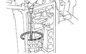
Using a screwdriver, remove the snap ring.
Tech Tips
Tape up the screwdriver tip before use.
-
Remove the 2nd brake pack.
-
-
INSPECT PACK CLEARANCE OF 1ST AND REVERSE BRAKE
-
Using a feeler gauge, measure the clearance between the plate and the 2nd brake drum.
Standard clearance 0.70 to 1.22 mm (0.0276 to 0.0480 in.) If the clearance is outside the standard range, select another flange.
Flange thickness No. Thickness No. Thickness 67 5.4 mm (0.213 in.) 52 4.6 mm (0.181 in.) 66 5.2 mm (0.205 in.) 53 4.4 mm (0.173 in.) 50 5.0 mm (0.197 in.) 54 4.2 mm (0.165 in.) 51 4.8 mm (0.189 in.) 55 4.0 mm (0.157 in.)
-
-
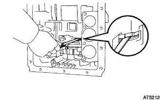
REMOVE 2ND BRAKE PISTON SLEEVE
-
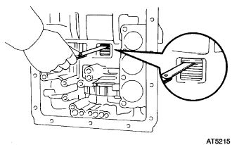
Using a screwdriver, remove the 2nd brake piston sleeve.
Tech Tips
Tape up the screwdriver tip before use.
-
-
REMOVE REAR PLANETARY GEAR ASSEMBLY
-
Using SST and a screwdriver, remove the snap ring.
- SST
- 09350-30020 ( 09350-07060 )
-
Remove the 2nd brake piston assembly, the 1st and reverse brake pack, the rear planetary gear assembly and the output shaft.
-
Remove the 2nd brake piston assembly.
-
Remove the 1st and reverse brake pack.
-
Remove the leaf spring.
-
-
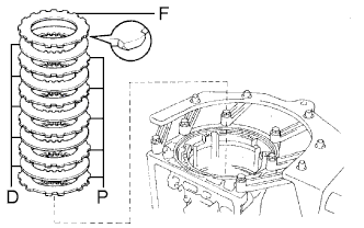
INSPECT 1ST AND REVERSE BRAKE CLUTCH DISC
-
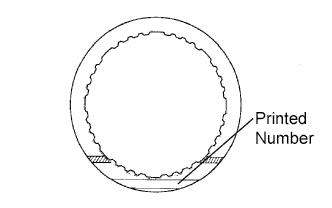
Check if the sliding surfaces of the disc, the plate and the flange are worn or burnt. If necessary, replace them.
Tech Tips
-
If the lining of the disc is peeled off or discolored, or even if only a part of the printed numbers is corroded, replace all discs.
-
Before assembling new discs, soak them in ATF for at least 15 minutes.
-
-
-
REMOVE BRAKE DRUM GASKET
-
Remove the brake drum gasket.
-
-
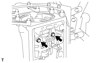
INSPECT PISTON STROKE OF 1ST AND REVERSE BRAKE
-
Make sure that the No. 2 1st and reverse brake piston move smoothly when applying and releasing compressed air into the transmission case.
-
-
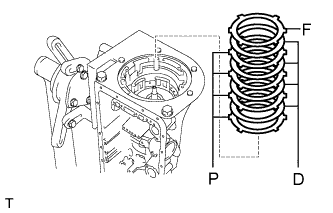
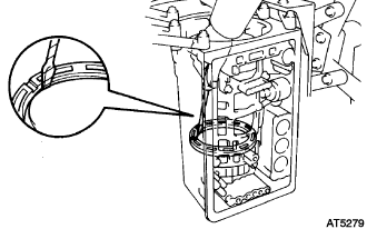
REMOVE 1ST AND REVERSE BRAKE RETURN SPRING SUB-ASSEMBLY
-
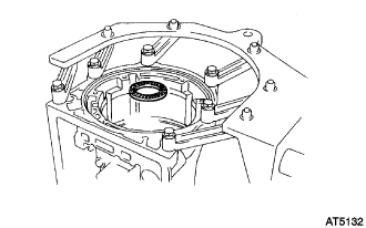
Remove the thrust needle roller bearing from the automatic transmission case sub-assembly.
-
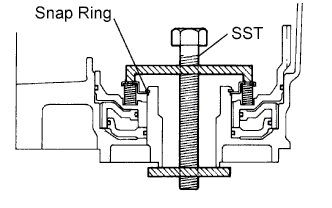
Set SST on the spring retainer, and compress the return spring.
- SST
- 09350-30020 ( 09350-07050 )
Note
Stop compressing when the spring retainer is lowered to a position 1 to 2 mm (0.039 to 0.078 in.) from the snap ring groove, preventing the spring retainer from being deformed.
-
Using snap ring pliers, remove the snap ring.
-
Remove the 1st and reverse brake return spring sub-assembly.
-
-
INSPECT 1ST AND REVERSE BRAKE RETURN SPRING SUB-ASSEMBLY
-
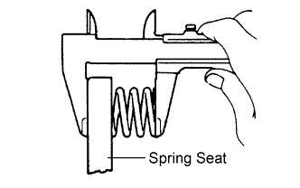
Check the return spring free length together with the spring seat.
Standard free length 18.39 mm (0.7240 in.) If the free length is shorter than the standard free length, replace the 1st and reverse brake return spring sub-assembly.
-
-
REMOVE NO. 2 1ST AND REVERSE BRAKE PISTON
-
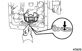
Hold the No. 2 1st and reverse brake piston by hand, and apply compressed air (392 kPa, 4.0 kgf/cm2, 57 psi) to the transmission case to remove the No. 2 1st and reverse brake piston.
If the piston does not pop out with compressed air, lift the piston out with needle-nose pliers.
-
Remove the O-ring from the No. 2 1st and reverse brake piston.
-
-
REMOVE BRAKE REACTION SLEEVE
-
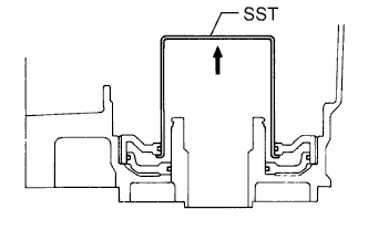
Install SST behind the brake reaction sleeve and gradually lift it out of the automatic transmission case sub-assembly.
- SST
- 09350-30020 ( 09350-07080 )
-
Remove the O-ring from the brake reaction sleeve.
-
-
REMOVE NO. 1 1ST AND REVERSE BRAKE PISTON
-
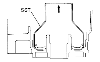
Install SST behind the No. 1 1st and reverse brake piston and gradually lift it out of the automatic transmission case sub-assembly.
- SST
- 09350-30020 ( 09350-07090 )
-
Remove the 2 O-rings from the No. 1 1st and reverse brake piston.
-
-
INSPECT AUTOMATIC TRANSMISSION CASE SUB-ASSEMBLY
-
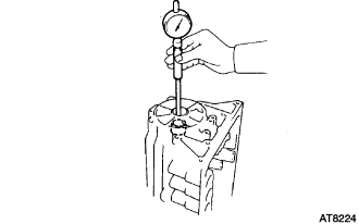
Using a cylinder gauge, measure the inside diameter of the automatic transmission case rear bushing.
Maximum inside diameter 38.13 mm (1.5012 in.) If the inside diameter is greater than the maximum, replace the automatic transmission case sub-assembly.
-