BRAKE CONTROL SYSTEM
-
OUTLINE
-
A brake control system [Anti-lock Brake system (ABS), Electronic Brake Force Distribution (EBD), brake assist, Traction Control (TRC), Vehicle Stability Control (VSC), steering cooperative control, hill-start assist control and trailer sway control] is provided.
-
The brake actuator and the skid control ECU have been integrated and a brake booster with master cylinder assembly has been provided, optimizing the hydraulic circuit and offering a weight reduction.
-
An electronically controlled brake system is used to control the hydraulic pressure at the 4 wheels.
-
A regenerative brake cooperative control is used.
-
-
MAIN FEATURES
-
Electronically Controlled Brake System
-
In this system, the conventional brake booster portion has been discontinued. Instead, the system consists of a brake booster with master cylinder assembly (consists of skid control ECU, brake actuator, brake master cylinder and brake master stroke simulator cylinder assembly) and brake booster pump assembly.
-
During normal braking, the fluid pressure generated by the master cylinder sub-assembly does not directly actuate the wheel cylinders, but serves as a hydraulic pressure signal. Instead, the actual control pressure is obtained by regulating the fluid pressure of the brake booster pump assembly, which actuates the wheel cylinders.
-
When the skid control ECU detects a fault in the system, brake force can be ensured by applying the brake using the fluid pressure boosted by the brake master cylinder.

-
-
Regenerative Brake Cooperative Control
-
Regenerative braking consists of a resistance force that is generated at the rotational axle in the reverse direction of the rotation of the generator (MG2) that is generating electricity. The greater the generated amperage (battery charging amperage), the greater the resistance force will be.
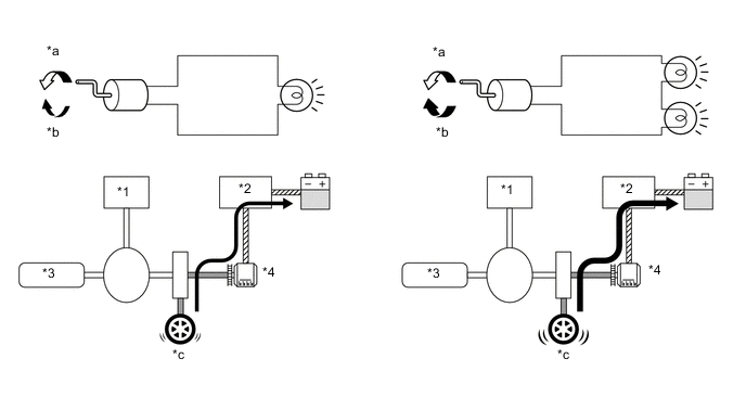
*1 Generator (MG1) *2 Inverter *3 Engine *4 Motor (MG2) *a Rotation Direction for Electricity Generation *b Resistance Force *c Brake Force - - -
The drive wheels and MG2 are joined mechanically. When the drive wheels rotate MG2 and cause it to operate as a generator, the regenerative brake force of MG2 is transmitted to the drive wheels. Based on the signals from the skid control ECU, this force is controlled by the hybrid system, which controls the generation of electricity.
-
Regenerative brake cooperative control does not rely solely on the braking force of the hydraulic brake system to supply the brake force required by the driver. Instead, by effecting cooperative control with the hybrid system, this control provides a joint braking force provided by the regenerative braking and the hydraulic braking. As a result, this control minimizes the loss of kinetic energy associated with normal hydraulic braking, and recovers energy by converting it into electrical energy.
-
The apportioning of the brake force between the hydraulic braking and the regenerative braking varies by the vehicle speed and braking time.
-
The apportioning of the brake force between the hydraulic braking and the regenerative braking is accomplished by controlling the hydraulic braking so that the total brake force of the hydraulic braking and the regenerative braking matches the brake force required by the driver.
-
If the regenerative braking becomes inoperative due to a malfunction in the hybrid system, the brake system effects control so that the entire brake force required by the driver is supplied by the hydraulic brake system.

-
-