SFI SYSTEM(for Rear Air Fuel Ratio Sensor), Diagnostic DTC:P050A00
| DTC Code | DTC Name |
|---|---|
| P050A00 | Cold Start Idle Control System Performance |
MONITOR DESCRIPTION
Tech Tips
This DTC is applicable to w/ Canister Pump Module only.
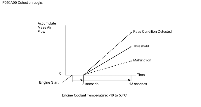
This monitor will run when the engine is started at an engine coolant temperature of -10 to 50°C (14 to 122°F). The DTC will be stored after the engine idles for 13 seconds (2 trip detection logic).
The DTC is designed to monitor the idle air control at cold start. When the engine is started at an engine coolant temperature of below 50°C (122°F), the ECM measures the accumulated mass air flow during engine idling. If the accumulated mass air flow does not reach the specified level within 10 seconds, the ECM interprets this as a malfunction. The MIL is illuminated and a DTC is stored when the malfunction is detected in consecutive driving cycles (2 trip detection logic).
The electronic throttle control system controls the idle speed. The electronic throttle control system operates the throttle actuator to open and close the throttle valve, and adjusts the intake air amount to achieve the target idle speed.
Note
The idle speed control learned values are cleared by performing a learned value reset. Idle speed control learning needs to be performed before this DTC can be stored.
Tech Tips
Idle speed control learning is performed when the engine is warmed up and has been idling for 5 minutes.
| DTC No. | Detection Item | DTC Detection Condition | Trouble Area | MIL | Memory | Note |
|---|---|---|---|---|---|---|
| P050A00 | Cold Start Idle Control System Performance | Insufficient mass air flow after a cold start (2 trip detection logic). |
|
Comes on | DTC stored | SAE Code: P050A |
MONITOR STRATEGY
| Required Sensors/Components (Main) | Throttle body with motor assembly |
| Required Sensors/Components (Related) | Mass air flow meter sub-assembly Engine coolant temperature sensor |
| Frequency of Operation | Once per driving cycle |
TYPICAL MALFUNCTION THRESHOLDS
| Accumulated mass air flow | Less than 60 g (varies with engine coolant temperature and engine coolant temperature at engine start) |
CONFIRMATION DRIVING PATTERN
-
Connect the GTS to the DLC3.
-
Turn the engine switch on (IG).
-
Turn the GTS on.
-
Clear the DTCs (even if no DTCs are stored, perform the clear DTC procedure).
-
Turn the engine switch off and wait for at least 30 seconds.
-
Start the engine and warm it up for 5 minutes or more.
-
Stop the engine.
-
Leave the vehicle outside overnight.
-
Turn the engine switch on (IG) [A].
-
Turn the GTS on.
-
Enter the following menus: Powertrain / Engine / Data List / Coolant Temperature.
-
Check that the value of the Data List item Coolant Temperature is between -10 and 50°C (14 and 122°F).
-
Start the engine and warm it up until the engine coolant temperature is the same as the coolant temperature in the Freeze Frame Data.
-
Idle the engine for 1 minute or more [B].
-
Enter the following menus: Powertrain / Engine / Trouble Codes [C].
-
Read the pending DTC.
Tech Tips
-
If a pending DTC is output, the system is malfunctioning.
-
If a pending DTC is not output, perform the following procedure.
-
-
Enter the following menus: Powertrain / Engine / Utility / All Readiness.
-
Input the DTC: P050A00.
-
Check the DTC judgment result.
GTS Display Description NORMAL
-
DTC judgment completed
-
System normal
ABNORMAL
-
DTC judgment completed
-
System abnormal
INCOMPLETE
-
DTC judgment not completed
-
Perform driving pattern after confirming DTC enabling conditions
Tech Tips
-
If the judgment result is NORMAL, the system is normal.
-
If the judgment result is ABNORMAL, the system is malfunctioning.
-
If the judgment result is INCOMPLETE, idle the engine for 3 minutes, let the engine cool down, and then perform steps [A] through [C] again.
-
CAUTION / NOTICE / HINT
Note
Inspect the fuses for circuits related to this system before performing the following procedure.
Tech Tips
Read Freeze Frame Data using the GTS. The ECM records vehicle and driving condition information as Freeze Frame Data the moment a DTC is stored. When troubleshooting, Freeze Frame Data can be helpful in determining whether the vehicle was moving or stationary, whether the engine was warmed up or not, whether the air fuel ratio was lean or rich, as well as other data recorded at the time of a malfunction.
PROCEDURE
-
CHECK ANY OTHER DTCS OUTPUT (IN ADDITION TO DTC P050A00)
-
Connect the GTS to the DLC3.
-
Turn the engine switch on (IG).
-
Turn the GTS on.
-
Enter the following menus: Powertrain / Engine / Trouble Codes.
-
Read the DTCs.
Powertrain > Engine > Trouble CodesResult Result Proceed to DTC P050A00 is output A DTC P050A00 and other DTCs are output B Tech Tips
If any DTCs other than P050A00 are output, troubleshoot those DTCs first.
B 
GO TO DTC CHART Click here
A 
-
-
READ VALUE USING GTS (FUEL TRIM)
Tech Tips
Calculate the total fuel trim values to check the characteristic deviation of the mass air flow meter sub-assembly.
-
Connect the GTS to the DLC3.
-
Start the engine.
-
Turn the GTS on.
-
Enter the following menus: Powertrain / Engine / Data List / Short FT B1S1 and Long FT B1S1.
Powertrain > Engine > Data ListTester Display Short FT B1S1 Long FT B1S1 -
Read the values displayed on the GTS at engine idle.
-
Add the Short FT B1S1 and Long FT B1S1 values to obtain the total fuel trim.
Standard GTS Display Specified Condition Total of Short FT B1S1 and Long FT B1S1 Between -20 and 20% Result Proceed to OK NG
NG 
CHECK PCV HOSE CONNECTIONS Click here
OK
-
-
INSPECT THROTTLE BODY WITH MOTOR ASSEMBLY (VISUALLY CHECK THROTTLE VALVE)
-
Check for foreign matter between the throttle valve and housing. If necessary, clean the throttle body with motor assembly. Also, check that the throttle valve moves smoothly.
OK Throttle valve is not contaminated with foreign matter and moves smoothly. Result Proceed to OK NG
OK
GO TO STEP 10 Click here
NG
-
-
REPLACE THROTTLE BODY WITH MOTOR ASSEMBLY
-
Replace the throttle body with motor assembly.
Tech Tips
Perform "Inspection After Repair" after replacing the throttle body with motor assembly.
Result Proceed to NEXT
NEXT
GO TO STEP 16 Click here
-
-
CHECK PCV HOSE CONNECTIONS
-
Check the PCV hose connections.
OK PCV valve and hose are connected correctly and are not damaged. Result Proceed to OK NG
NG
REPAIR OR REPLACE PCV HOSE Click here
OK
-
-
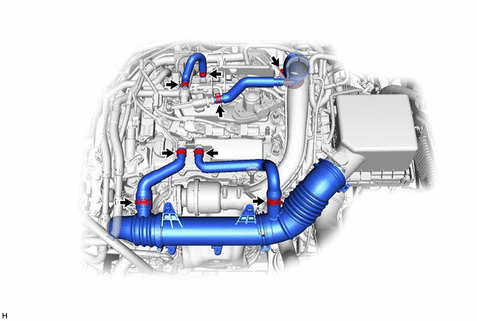
CHECK INTAKE SYSTEM
-
Check the intake system for vacuum leaks.
OK No leaks from the intake system. Result Proceed to OK NG
NG
REPAIR OR REPLACE INTAKE SYSTEM Click here
OK
-
-
CHECK AIR CLEANER FILTER ELEMENT SUB-ASSEMBLY
-
Visually check that the air cleaner filter element sub-assembly is not excessively contaminated with dirt or oil.
OK The air cleaner filter element sub-assembly is not excessively contaminated with dirt or oil. Result Proceed to OK NG
NG
REPLACE AIR CLEANER FILTER ELEMENT SUB-ASSEMBLY Click here
OK
-
-
PERFORM ACTIVE TEST USING GTS (OPERATE CAMSHAFT TIMING OIL CONTROL VALVE ASSEMBLY)
-
Operate the VVT system through the Active Test, and check if the VVT system is operating normally.
-
Perform the Active Test, referring to DTC P001100 Procedure (VVT system for intake camshaft).
-
Perform the Active Test, referring to DTC P001400 Procedure (VVT system for exhaust camshaft).
Result Proceed to OK NG -
NG
CHECK AND REPAIR VVT SYSTEM Click here
OK
-
-
READ VALUE USING GTS (MASS AIR FLOW SENSOR)
-
Connect the GTS to the DLC3.
-
Start the engine.
-
Turn the GTS on.
-
Enter the following menus: Powertrain / Engine / Data List / Engine Speed, Mass Air Flow Sensor and Coolant Temperature.
Powertrain > Engine > Data ListTester Display Engine Speed Mass Air Flow Sensor Coolant Temperature -
Allow the engine to idle until Coolant Temperature reaches 75°C (167°F) or higher.
-
Read Mass Air Flow Sensor while maintaining an engine speed of 3000 rpm.
Standard GTS Display Condition Specified Condition Mass Air Flow Sensor
-
Shift lever position: P
-
A/C: Off
-
Engine warmed up
-
Engine Speed: 3000 rpm
Between 6.0 and 18.0 gm/sec Result Proceed to OK NG -
NG
GO TO STEP 18 Click here
OK
-
-
CLEAR DTC
-
Connect the GTS to the DLC3.
-
Turn the engine switch on (IG).
-
Turn the GTS on.
-
Clear the DTCs.
Powertrain > Engine > Clear DTCs -
Turn the engine switch off and wait for at least 30 seconds.
Result Proceed to NEXT
NEXT
-
-
CHECK WHETHER DTC OUTPUT RECURS (DTC P050A00)
Note
In this operation, the engine must be cold (approximately the same as the engine coolant temperature recorded in the Freeze Frame Data).
-
Turn the engine switch on (IG).
-
Turn the GTS on.
-
Enter the following menus: Powertrain / Engine / Data List / Coolant Temperature.
Powertrain > Engine > Data ListTester Display Coolant Temperature -
Check that the engine coolant temperature is between -10 and 50°C (14 and 122°F).
-
Start the engine and warm it up until the engine coolant temperature is the same as the engine coolant temperature in the Freeze Frame Data.
-
Drive the vehicle in accordance with the driving pattern described in Confirmation Driving Pattern.
-
Enter the following menus: Powertrain / Engine / Utility / All Readiness.
Powertrain > Engine > UtilityTester Display All Readiness -
Input the DTC: P050A00.
-
Check the DTC judgment result.
Result Result Proceed to NORMAL
(DTCs are not output)
A ABNORMAL
(DTC P050A00 is output)
B
A
CHECK FOR INTERMITTENT PROBLEMS Click here
B
GO TO STEP 18 Click here
-
-
CHECK AND REPAIR VVT SYSTEM
-
Check and repair the VVT system.
Tech Tips
-
Refer to DTC P001100 Inspection Procedure (VVT-i system for intake camshaft)
-
Refer to DTC P001400 Inspection Procedure (VVT-i system for exhaust camshaft)
Result Proceed to NEXT -
NEXT
GO TO STEP 16 Click here
-
-
REPLACE AIR CLEANER FILTER ELEMENT SUB-ASSEMBLY
-
Replace the air cleaner filter element sub-assembly.
Result Proceed to NEXT
NEXT
GO TO STEP 16 Click here
-
-
REPAIR OR REPLACE INTAKE SYSTEM
-
Repair or replace the intake system.
Tech Tips
Perform "Inspection After Repair" after repairing or replacing the intake system.
Result Proceed to NEXT
NEXT
GO TO STEP 16 Click here
-
-
REPAIR OR REPLACE PCV HOSE
-
Repair or replace the PCV valve or hose.
Result Proceed to NEXT
NEXT
-
-
CLEAR DTC
-
Connect the GTS to the DLC3.
-
Turn the engine switch on (IG).
-
Turn the GTS on.
-
Clear the DTCs.
Powertrain > Engine > Clear DTCs -
Turn the engine switch off and wait for at least 30 seconds.
Result Proceed to NEXT
NEXT
-
-
CHECK WHETHER DTC OUTPUT RECURS (DTC P050A00)
Note
In this operation, the engine must be cold (approximately the same as the engine coolant temperature recorded in the Freeze Frame Data).
-
Turn the engine switch on (IG).
-
Turn the GTS on.
-
Enter the following menus: Powertrain / Engine / Data List / Coolant Temperature.
Powertrain > Engine > Data ListTester Display Coolant Temperature -
Check that the engine coolant temperature is between -10 and 50°C (14 and 122°F).
-
Start the engine and warm it up until the engine coolant temperature is the same as the engine coolant temperature in the Freeze Frame Data.
-
Drive the vehicle in accordance with the driving pattern described in Confirmation Driving Pattern.
-
Enter the following menus: Powertrain / Engine / Utility / All Readiness.
Powertrain > Engine > UtilityTester Display All Readiness -
Input the DTC: P050A00.
-
Check the DTC judgment result.
Result Result Proceed to NORMAL
(DTCs are not output)
A ABNORMAL
(DTC P050A00 is output)
B
A
END
B
-
-
CHECK HARNESS AND CONNECTOR (MASS AIR FLOW METER SUB-ASSEMBLY CONNECTOR CONNECTION)
-
Check the connection and terminal contact pressure of connectors and wire harnesses between the mass air flow meter sub-assembly and ECM.
Tech Tips
Repair any problems.
Result Proceed to NEXT
NEXT
-
-
CLEAR DTC
-
Connect the GTS to the DLC3.
-
Turn the engine switch on (IG).
-
Turn the GTS on.
-
Clear the DTCs.
Powertrain > Engine > Clear DTCs -
Turn the engine switch off and wait for at least 30 seconds.
Result Proceed to NEXT
NEXT
-
-
CHECK WHETHER DTC OUTPUT RECURS (DTC P050A00)
Note
In this operation, the engine must be cold (approximately the same as the engine coolant temperature recorded in the Freeze Frame Data).
-
Turn the engine switch on (IG).
-
Turn the GTS on.
-
Enter the following menus: Powertrain / Engine / Data List / Coolant Temperature.
Powertrain > Engine > Data ListTester Display Coolant Temperature -
Check that the engine coolant temperature is between -10 and 50°C (14 and 122°F).
-
Start the engine and warm it up until the engine coolant temperature is the same as the engine coolant temperature in the Freeze Frame Data.
-
Drive the vehicle in accordance with the driving pattern described in Confirmation Driving Pattern.
-
Enter the following menus: Powertrain / Engine / Utility / All Readiness.
Powertrain > Engine > UtilityTester Display All Readiness -
Input the DTC: P050A00.
-
Check the DTC judgment result.
Result Result Proceed to NORMAL
(DTCs are not output)
A ABNORMAL
(DTC P050A00 is output)
B
A
END
B
-
-
CHECK HARNESS AND CONNECTOR (MASS AIR FLOW METER SUB-ASSEMBLY - ECM)
-
Disconnect the mass air flow meter sub-assembly connector.
-
Disconnect the ECM connector.
-
Measure the resistance according to the value(s) in the table below.
Standard Resistance Tester Connection Condition Specified Condition D9-5 (VG) - D1-92 (VG) Always Below 1 Ω D9-4 (E2G) - D1-91 (E2G) Always Below 1 Ω D9-5 (VG) or D1-92 (VG) - Body ground and other terminals Always 10 kΩ or higher Result Proceed to OK NG
NG
REPAIR OR REPLACE HARNESS OR CONNECTOR
OK
-
-
REPLACE MASS AIR FLOW METER SUB-ASSEMBLY
-
Replace the mass air flow meter sub-assembly.
Tech Tips
-
If the result of the inspection performed in step 9 (READ VALUE USING GTS (MASS AIR FLOW SENSOR)) indicated no problem, proceed to the next step without replacing the mass air flow meter sub-assembly.
-
Perform "Inspection After Repair" after replacing the mass air flow meter sub-assembly.
Result Proceed to NEXT -
NEXT
-
-
CLEAR DTC
-
Connect the GTS to the DLC3.
-
Turn the engine switch on (IG).
-
Turn the GTS on.
-
Clear the DTCs.
Powertrain > Engine > Clear DTCs -
Turn the engine switch off and wait for at least 30 seconds.
Result Proceed to NEXT
NEXT
-
-
CONFIRM WHETHER MALFUNCTION HAS BEEN SUCCESSFULLY REPAIRED
Note
In this operation, the engine must be cold (approximately the same as the engine coolant temperature recorded in the Freeze Frame Data).
-
Turn the engine switch on (IG).
-
Turn the GTS on.
-
Enter the following menus: Powertrain / Engine / Data List / Coolant Temperature.
Powertrain > Engine > Data ListTester Display Coolant Temperature -
Check that the engine coolant temperature is between -10 and 50°C (14 and 122°F).
-
Start the engine and warm it up until the engine coolant temperature is the same as the engine coolant temperature in the Freeze Frame Data.
-
Drive the vehicle in accordance with the driving pattern described in Confirmation Driving Pattern.
-
Enter the following menus: Powertrain / Engine / Utility / All Readiness.
Powertrain > Engine > UtilityTester Display All Readiness -
Input the DTC: P050A00.
-
Check the DTC judgment result.
Result Result Proceed to NORMAL
(DTCs are not output)
A ABNORMAL
(DTC P050A00 is output)
B
A
END
B
REPLACE ECM Click here
-