FRONT AXLE HUB REMOVAL
CAUTION / NOTICE / HINT
The necessary procedures (adjustment, calibration, initialization, or registration) that must be performed after parts are removed and installed, or replaced during front axle hub sub-assembly removal/installation are shown below.
| Replaced Part or Performed Procedure | Necessary Procedure | Effect/Inoperative Function when Necessary Procedure not Performed | Link |
|---|---|---|---|
| Front wheel alignment adjustment |
|
|
Tech Tips
-
Use the same procedure for the RH side and LH side.
-
The following procedure is for the LH side.
PROCEDURE
-
REMOVE FRONT WHEEL
-
REMOVE FRONT AXLE SHAFT NUT
-
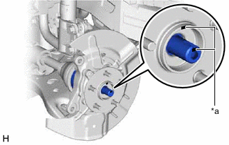
SEPARATE FRONT SPEED SENSOR (w/o AVS)
-
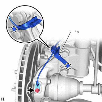
*a Sensor Clamp Disengage the 2 claws and separate the sensor clamp.
-
Remove the bolt and separate the front speed sensor from the steering knuckle.
Note
-
Prevent foreign matter from contacting the sensor tip.
-
Be careful not to damage the front speed sensor.
-
Clean the speed sensor installation hole and the contact surfaces every time the speed sensor is removed.
-
-
-
SEPARATE FRONT SPEED SENSOR (w/ AVS)
-
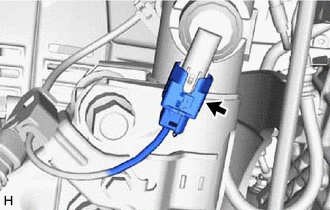
Disconnect the AVS connector from the absorber control actuator.
-
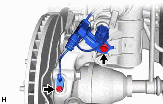
Remove the 2 bolts and separate the front speed sensor from the front shock absorber assembly and steering knuckle.
Note
-
Prevent foreign matter from contacting the sensor tip.
-
Be careful not to damage the front speed sensor.
-
Clean the speed sensor installation hole and the contact surfaces every time the speed sensor is removed.
-
-
-
SEPARATE TIE ROD ASSEMBLY
-
SEPARATE FRONT DISC BRAKE CALIPER ASSEMBLY
-
REMOVE FRONT DISC
-
SEPARATE FRONT LOWER NO. 1 SUSPENSION ARM SUB-ASSEMBLY
-
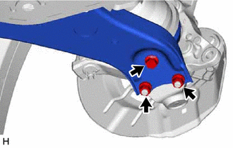
Remove the bolt, 2 nuts and separate the front lower No. 1 suspension arm sub-assembly from the front lower ball joint assembly.
-
-
SEPARATE FRONT DRIVE SHAFT ASSEMBLY
-
*a Matchmark Put matchmarks on the front drive shaft assembly and the front axle hub sub-assembly.
-
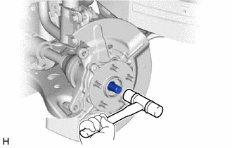
Using a plastic hammer, separate the front drive shaft assembly from the front axle assembly.
Note
-
Be careful not to damage the drive shaft boot.
-
Do not push the front axle assembly towards the outside of the vehicle any further than necessary.
Tech Tips
If it is difficult to separate the front drive shaft assembly from the front axle assembly, tap the end of the front drive shaft assembly using a brass bar and a hammer.
-
-
-
REMOVE FRONT AXLE ASSEMBLY
-
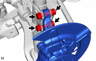
Remove the 2 bolts, 2 nuts and front axle assembly from the front shock absorber assembly.
Note
When removing the nuts, keep the bolts from rotating.
-
-
REMOVE FRONT AXLE HUB SUB-ASSEMBLY
-
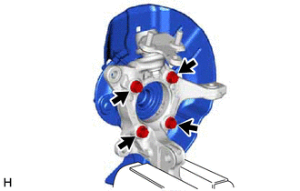
Secure the front axle assembly between aluminum plates in a vise.
Note
Do not overtighten the vise.
-
Remove the 4 bolts, front axle hub sub-assembly and front disc brake dust cover from the steering knuckle.
Note
-
Do not drop the front axle hub sub-assembly.
-
Be careful not to damage the speed sensor rotor or contact surfaces.
-
Do not allow foreign matter to contact the speed sensor rotor or contact surfaces.
-
-