CENTER POWER OUTLET SOCKET(for Console Box Front Side) REMOVAL
PROCEDURE
-
REMOVE REMOTE TOUCH ASSEMBLY
-
REMOVE LOWER NO. 2 INSTRUMENT PANEL FINISH PANEL
-
REMOVE LOWER NO. 1 INSTRUMENT PANEL FINISH PANEL
-
REMOVE SHIFT LEVER KNOB SUB-ASSEMBLY
-
REMOVE INSTRUMENT CLUSTER FINISH PANEL ORNAMENT
-
REMOVE CONSOLE PANEL SUB-ASSEMBLY
-
REMOVE REAR CONSOLE BOX GARNISH
-
REMOVE NO. 2 POWER OUTLET SOCKET ASSEMBLY
-
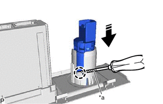
*a Protective Tape 
Remove in this Direction Using a screwdriver with its tip wrapped with protective tape, disengage the claw and remove the No. 2 power outlet socket assembly as shown in the illustration.
-
-
REMOVE NO. 2 POWER OUTLET SOCKET COVER
-
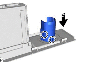
Remove in this Direction Disengage the 2 claws and remove the No. 2 power outlet socket cover as shown in the illustration.
-