CAMSHAFT REMOVAL
PROCEDURE
REMOVE CHAIN SUB-ASSEMBLY
INSPECT CAMSHAFT TIMING GEAR ASSEMBLY
-
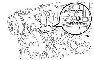
*1
Adhesive Tape
*a
Prick a Hole
*b
Adhesive Tape Sealing Area
Inspect the lock of the camshaft timing gear assembly.
After cleaning and degreasing the VVT oil hole on the intake side of the No. 1 camshaft bearing cap, completely seal the oil hole with adhesive tape or equivalent as shown in the illustration to prevent air from leaking.
Note:Be sure to cover the oil hole completely because air leaks due to insufficient sealing will prevent the lock pin from being released.
Prick a hole in the tape covering the oil hole as shown in the illustration. (Procedure A)
-
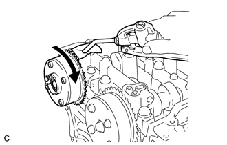
Apply approximately 150 kPa (1.5 kgf/cm2, 22 psi) of air pressure to the hole pricked in procedure A to release the lock pin.
Note:If air leaks out, reattach the adhesive tape.
Cover the oil hole with a piece of cloth when applying air pressure to prevent oil from spraying.
Forcibly turn the camshaft timing gear assembly in the advance direction (counterclockwise).
Tip:Depending on the air pressure applied, the camshaft timing gear assembly may turn in the advance direction without assistance.
-
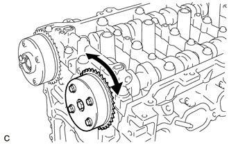
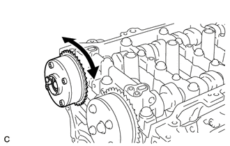
Turn the camshaft timing gear assembly within its movable range (26.5 to 28.5°) 2 or 3 times without turning it to the most retarded position. Make sure that the camshaft timing gear assembly turns smoothly.
Remove the adhesive tape from the No. 1 camshaft bearing cap.
-
INSPECT CAMSHAFT TIMING EXHAUST GEAR ASSEMBLY
-
*1
Adhesive Tape
*a
Prick a Hole
*b
Adhesive Tape Sealing Area
Check the lock of the camshaft timing exhaust gear assembly.
After cleaning and degreasing the VVT oil hole on the exhaust side of the No. 1 camshaft bearing cap, completely seal the oil hole with adhesive tape or equivalent as shown in the illustration to prevent air from leaking.
Note:Be sure to cover the oil hole completely because air leaks due to insufficient sealing will prevent the lock pin from being released.
Prick a hole in the tape covering the oil hole as shown in the illustration. (Procedure A)
-
Apply approximately 200 kPa (2.0 kgf/cm2, 28 psi) of air pressure to the hole pricked in procedure A to release the lock pin.
Note:If air leaks out, reattach the adhesive tape.
Cover the oil hole with a piece of cloth when applying air pressure to prevent oil from spraying.
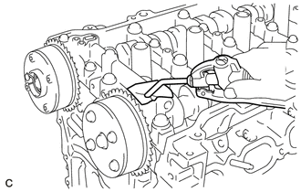
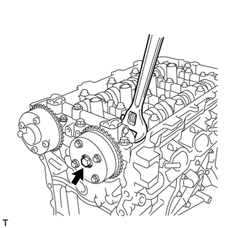
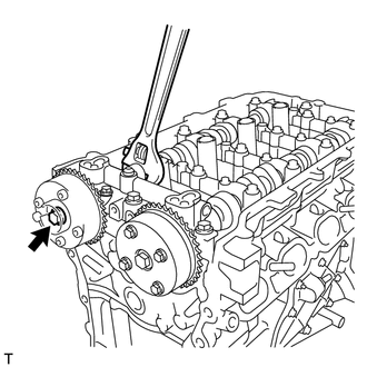
Using a screwdriver with its tip wrapped with tape, forcibly turn the camshaft timing exhaust gear assembly in the retard direction (clockwise).
Note:Be sure to keep the camshaft timing exhaust gear assembly in the retard direction using a screwdriver. If the gear is released, it will return to the most advanced position automatically due to the force from the spring.
Do not damage the camshaft timing exhaust gear assembly.
-
Using a screwdriver with its tip wrapped with tape, turn the camshaft timing exhaust gear assembly within its movable range (19 to 21°) 2 or 3 times without turning it to the most advanced position. Make sure that the camshaft timing exhaust gear assembly turns smoothly.
Remove the adhesive tape from the No. 1 camshaft bearing cap.
-
REMOVE CAMSHAFT TIMING GEAR ASSEMBLY
-
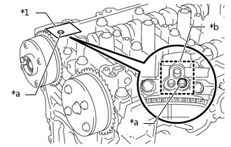
Remove the flange bolt while holding the hexagonal portion of the camshaft, and then remove the camshaft timing gear assembly.
Note: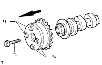
*1
Flange Bolt
*a
Do Not Remove
Before removing the camshaft timing gear assembly, make sure that the lock pin has been released.
Be sure not to remove the other 4 bolts.
Keep the camshaft timing gear horizontal while removing it from the camshaft.
-
REMOVE CAMSHAFT TIMING EXHAUST GEAR ASSEMBLY
-
Remove the flange bolt while holding the hexagonal portion of the No. 2 camshaft, and then remove the camshaft timing exhaust gear assembly.
Note: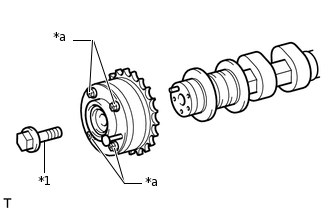
*1
Flange Bolt
*a
Do Not Remove
Be sure not to remove the other 4 bolts.
Keep the camshaft timing exhaust gear horizontal while removing it from the No. 2 camshaft.
-
REMOVE CAMSHAFT BEARING CAP
-
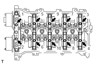
Uniformly loosen and remove the 10 bearing cap bolts in the sequence shown in the illustration.
-
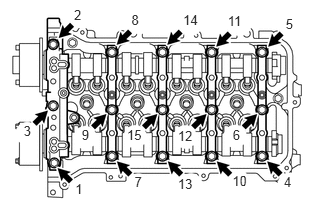
Uniformly loosen and remove the 15 bearing cap bolts in the sequence shown in the illustration.
Note:Uniformly loosen the bolts while keeping the camshaft level.
Remove the 5 camshaft bearing caps.
Tip:Arrange the removed parts in the correct order.
-
REMOVE CAMSHAFT
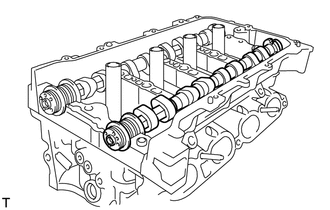
REMOVE NO. 2 CAMSHAFT
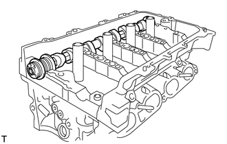
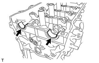
REMOVE NO. 1 CAMSHAFT BEARING
-
Remove the 2 No. 1 camshaft bearings.
-
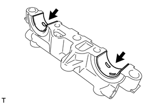
REMOVE NO. 2 CAMSHAFT BEARING
-
Remove the 2 No. 2 camshaft bearings.
-
REMOVE NO. 1 VALVE ROCKER ARM SUB-ASSEMBLY
REMOVE VALVE LASH ADJUSTER ASSEMBLY
REMOVE CAMSHAFT HOUSING SUB-ASSEMBLY
-
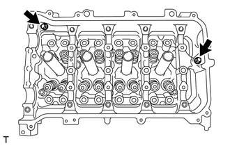
Remove the 2 bolts.
-
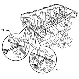
*1
Protective Tape
Remove the camshaft housing sub-assembly by prying between the cylinder head sub-assembly and camshaft housing sub-assembly with a screwdriver.
Note:Be careful not to damage the contact surfaces of the cylinder head sub-assembly and camshaft housing sub-assembly.
Tip:Tape the screwdriver tip before use.
-
INSPECT NO. 1 VALVE ROCKER ARM SUB-ASSEMBLY
INSPECT VALVE LASH ADJUSTER ASSEMBLY