РАСПРЕДВАЛ (для ряда 2) СНЯТИЕ
-
DISCONNECT BATTERY NEGATIVE TERMINAL
CAUTION:
Wait at least 90 seconds after disconnecting the cable from the negative (-) battery terminal to prevent airbag and seat belt pretensioner activation.
-
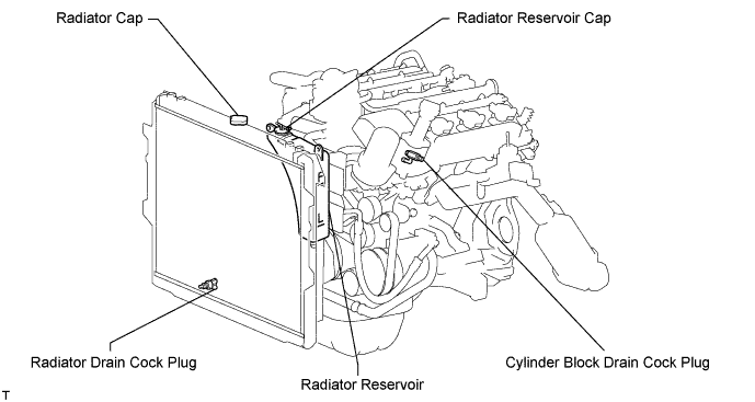
DRAIN ENGINE COOLANT
-
Remove the radiator cap.
-
Loosen the cylinder block drain cock plug and radiator drain plug, and then the coolant.
Tech Tips
Collect the coolant in a container and dispose of it according to the regulations in your area.
-
-
REMOVE V-BANK COVER
-
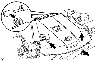
Отверните 2 гайки и снимите декоративную крышку V-образного двигателя.
-
-
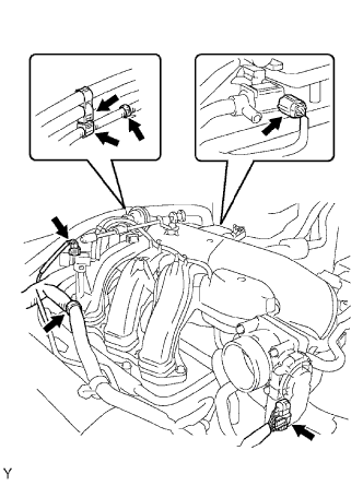
DISCONNECT NO. 2 VENTILATION HOSE
-
REMOVE AIR CLEANER
-
Отсоедините вакуумный шланг.
-
Отсоедините разъем датчика массового расхода воздуха.
-
Снимите 2 зажима жгута проводов.
-
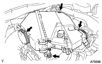
Ослабьте 2 хомута шланга.
-
Выверните 2 болта и снимите воздушный фильтр.
-
-
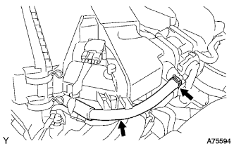
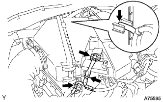
REMOVE INTAKE AIR SURGE TANK
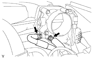
-
Отсоедините 2 перепускных шланга охлаждающей жидкости.
-
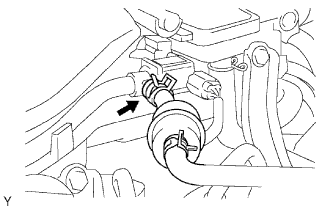
Отсоедините продувочный шланг.
-
Отсоедините вентиляционный шланг.
-
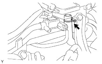
Отсоедините 2 разъема VSV.
-
Отсоедините разъем, соединяющий корпус дроссельной заслонки с электродвигателем.
-
Освободите 3 зажима жгута проводов и хомут шланга.
-
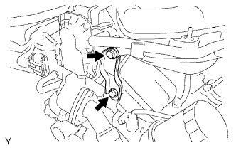
Выверните 2 болта и снимите кронштейн корпуса дроссельной заслонки.
-
Выверните болт и снимите отражатель масляного поддона.
-
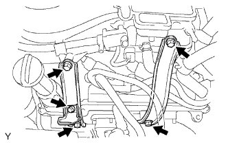
Выверните 4 болта и снимите 2 стойки уравнительного бачка.
-
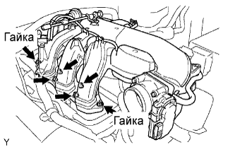
Отверните 2 гайки.
-
С помощью шестигранной торцевой головки на 8 мм выверните 4 болта и снимите уравнительный бачок с прокладкой.
-
-
REMOVE IGNITION COIL
-
REMOVE CYLINDER HEAD COVER RH
-
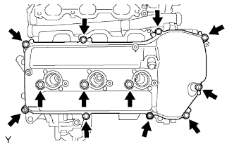
Remove the 10 bolts, 3 seal washers, 2 nuts, head cover and gasket.
-
-
REMOVE CYLINDER HEAD COVER LH
-
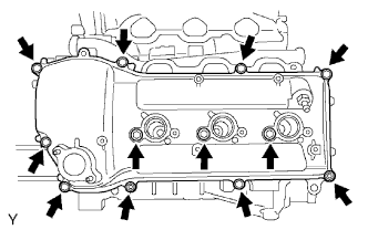
Remove the 10 bolts, 3 seal washers, 2 nuts, cylinder head cover and gasket.
-
Remove the ventilation valve from the cylinder head cover.
-
-
SET NO. 1 CYLINDER TO TDC/COMPRESSION
-
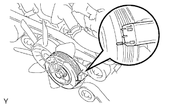
Turn the crankshaft pulley, and align its groove with the timing mark 0 of the timing chain cover.
-
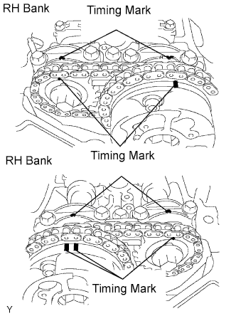
Check that the timing marks of the camshaft timing gears are aligned with the timing marks of the bearing cap as shown in the illustration.
If not, turn the crankshaft 1 complete revolution (360°) and align the timing marks as above.
-
-
REMOVE NO. 1 CHAIN TENSIONER
Note
-
Never rotate the crankshaft with the chain tensioner removed.
-
When rotating the camshaft with the timing chain removed, rotate the crankshaft counterclockwise 40° from the TDC before rotating it.
-
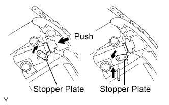
While rotating the stopper plate of the tensioner upward, push in the plunger of the chain tensioner as shown in the illustration.
-
While rotating the stopper plate of the tensioner downward, insert a bar of diameter of 3.5 mm (0.138 in.) into the holes in the stopper plate and tensioner to fix the stopper plate.
-
Remove the 2 bolts and chain tensioner.
-
-
REMOVE NO. 4 CAMSHAFT
Note
As the thrust clearance of the camshaft is small, the camshaft must be kept level while it is being removed. If the camshaft is not kept level, the portion of the cylinder head which receives the shaft thrust may crack or be damaged, causing the camshaft to seize or break. To avoid this, the following steps should be carried out.
-
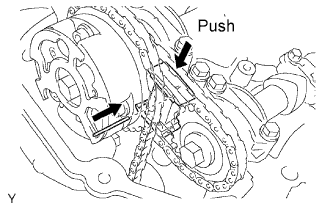
While pushing down the No. 3 chain tensioner, insert a diameter of 1.0 mm (0.039 in.) into the hole to fix it in place.
-
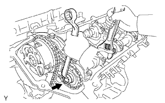
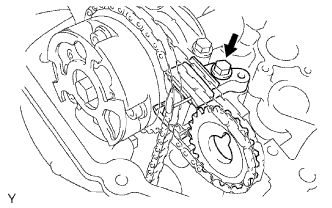
Hold the hexagonal portion of the No. 4 camshaft with a wrench, and remove the camshaft timing gear set bolt.
Note
Be careful not to damage the cylinder head and valve lifter with the wrench.
-
Separate the camshaft timing gear from the No. 4 camshaft.
-
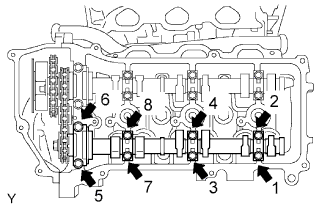
Uniformly loosen and remove the 8 bearing cap bolts in several passes in the sequence shown in the illustration.
-
Remove the 4 bearing caps and No. 4 camshaft.
-
-
REMOVE NO. 3 CHAIN TENSIONER
-
Remove the No. 3 chain tensioner bolt, and then remove the No. 3 chain tensioner and camshaft timing gear.
-
-
REMOVE NO. 3 CAMSHAFT
Note
As the thrust clearance of the camshaft is small, the camshaft must be kept level while it is being removed. If the camshaft is not kept level, the portion of the cylinder head which receives the shaft thrust may crack or be damaged, causing the camshaft to seize or break. To avoid this, the following steps should be carried out.
-
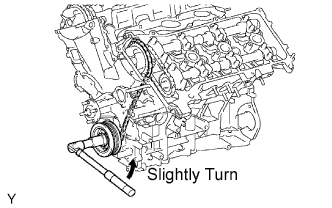
Release the chain tension between the camshaft timing gear (LH bank) and crankshaft timing gear by turning the crankshaft pulley counterclockwise slightly.
-
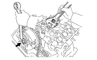
Hold the hexagonal portion of the No. 3 camshaft with a wrench, and loosen the camshaft timing gear set bolt.
Note
-
Be careful not to damage the cylinder head and valve lifter with the wrench.
-
Do not disassemble the camshaft timing gear assembly.
-
-
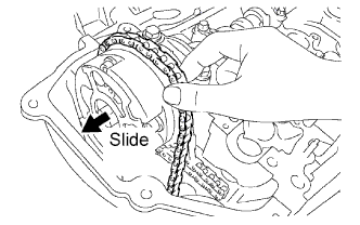
Slide the camshaft timing gear and separate the No. 1 chain from the camshaft timing gear.
-
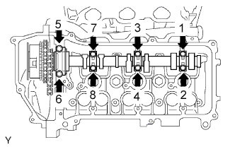
Uniformly loosen and remove the 8 bearing cap bolts in several passes in the sequence shown in the illustration.
-
Remove the 4 bearing caps.
-
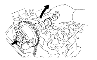
Remove the camshaft timing gear set bolt with the No. 3 camshaft is lifted up, and then remove the No. 3 camshaft and camshaft timing gear with No. 2 chain.
-
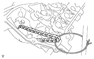
Tie the No.1 chain with a string as shown in the illustration.
Note
Be careful not to drop anything inside the timing chain cover.
-