PRE-COLLISION SYSTEM Pre-collision System Switch Circuit
| DTC Code | DTC Name |
|---|---|
| Pre-collision System Switch Circuit |
DESCRIPTION
Each time the pre-collision system cancel switch is pressed, the multi-information display sensitivity setting display changes and the sensitivity of the pre-collision system changes between 3 levels. Also, when the switch is pressed and held, the pre-collision system cancels.
WIRING DIAGRAM
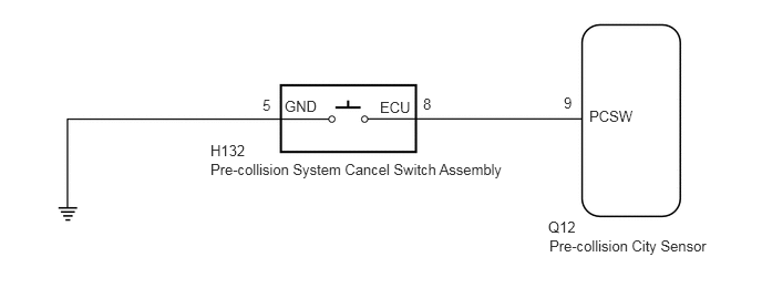
PROCEDURE
CHECK HARNESS AND CONNECTOR
Disconnect the H132 pre-collision system cancel switch connector.
Disconnect the Q12 pre-collision city sensor connector.
Measure the resistance according to the value(s) in the table below.
Standard Resistance
Tester Connection
Condition
Specified Condition
H132-8 (ECU) - Q12-9 (PCSW)
Always
Below 1 Ω
H132-5 (GND) - Body ground
Always
Below 1 Ω
H132-8 (ECU) - Body ground
Always
10 kΩ or higher
Connect the Q12 pre-collision city sensor connector.
Connect the H132 pre-collision system cancel switch connector.
REPAIR OR REPLACE HARNESS OR CONNECTOR
INSPECT PRE-COLLISION SYSTEM CANCEL SWITCH
Remove the pre-collision system cancel switch (Click here).
Inspect the pre-collision system cancel switch (Click here).