CRUISE CONTROL SYSTEM TC and CG Terminal Circuit
| DTC Code | DTC Name |
|---|---|
| TC and CG Terminal Circuit |
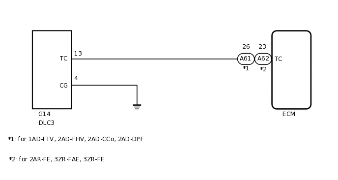
WIRING DIAGRAM
PROCEDURE
CHECK HARNESS AND CONNECTOR (DLC3 - ECM AND BODY GROUND)
for 1AD-FTV, 2AD-FHV, 2AD-CCo, 2AD-DPF
Disconnect the A61 ECM connector.
Measure the resistance according to the value(s) in the table below.
Standard Resistance
Tester Connection
Condition
Specified Condition
G14-13 (TC) - A61-26 (TC)
Always
Below 1 Ω
G14-4 (CG) - Body ground
Always
Below 1 Ω
G14-13 (TC) or A61-26 (TC) - Body ground
Always
10 kΩ or higher
for 2AR-FE, 3ZR-FAE, 3ZR-FE
Disconnect the A62 ECM connector.
Measure the resistance according to the value(s) in the table below.
Standard Resistance
Tester Connection
Condition
Specified Condition
G14-13 (TC) - A62-23 (TC)
Always
Below 1 Ω
G14-4 (CG) - Body ground
Always
Below 1 Ω
G14-13 (TC) or A62-23 (TC) - Body ground
Always
10 kΩ or higher
Result
Proceed to
OK
NG
NG REPAIR OR REPLACE HARNESS OR CONNECTOR