ENGINE UNIT REASSEMBLY
CAUTION / NOTICE / HINT
Perform "Inspection After Repair" after replacing the engine coolant temperature sensor.
PROCEDURE
INSTALL RING PIN
Note:It is not necessary to remove the ring pins unless they are being replaced.
-
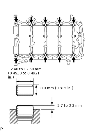
Using a plastic-faced hammer, tap in 10 new ring pins to the specified protrusion height.
Protrusion height
2.7 to 3.3 mm (0.106 to 0.130 in.)
-
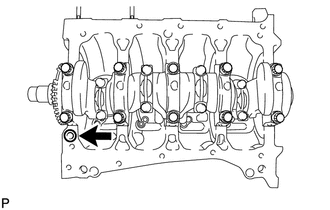
INSTALL STRAIGHT PIN
Note:It is not necessary to remove the straight pins unless they are being replaced.
-
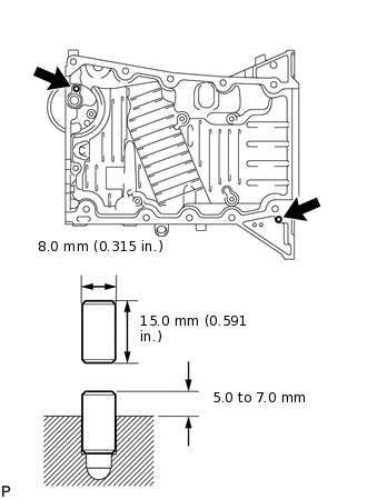
Using a plastic-faced hammer, tap in 2 new straight pins to the specified protrusion height.
Protrusion height
5.0 to 7.0 mm (0.197 to 0.276 in.)
-
INSTALL OIL STRAINER SUB-ASSEMBLY
-
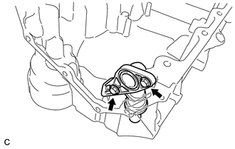
Install the oil strainer sub-assembly to the oil pan sub-assembly with the 2 bolts.
10 N*m
102 kgf*cm
7 ft.*lbf
-
INSTALL NO. 1 OIL PAN BAFFLE PLATE
-
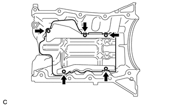
Install the No. 1 oil pan baffle plate to the oil pan sub-assembly with the 5 bolts.
10 N*m
102 kgf*cm
7 ft.*lbf
-
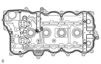
INSTALL OIL PAN SUB-ASSEMBLY
-
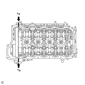
Install a new gasket to the cylinder block sub-assembly.
Apply seal packing to the places shown in the illustration.
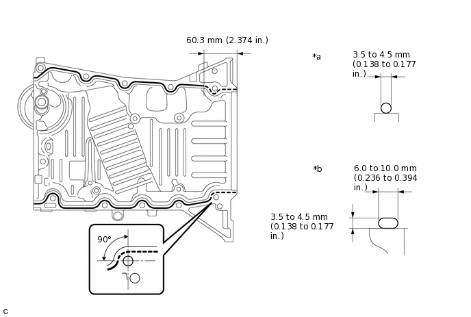
*a
Continuous Line Area
*b
Dashed Line Area
Seal packing
Toyota Genuine Seal Packing Black, Three Bond 1207B or equivalent
Note:Remove any oil from the contact surfaces.
Install the oil pan sub-assembly within 3 minutes of applying seal packing.
Do not start the engine for at least 2 hours after installation.
Apply adhesive to the threads of the bolt (C).
Adhesive
Toyota Genuine Adhesive 1324, Three Bond 1324 or equivalent
Tip:Apply adhesive to the bolt (C) more than 7.0 mm (0.276 in.) from the bolt end.
-
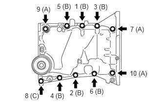
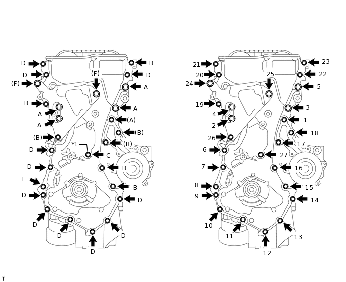
Install the oil pan sub-assembly with the 10 bolts in the sequence shown in the illustration.
21 N*m
214 kgf*cm
15 ft.*lbf
Bolt Length
Item
Length
Bolt A
55 mm (2.165 in.)
Bolt B
30 mm (1.181 in.)
Bolt C
30 mm (1.181 in.)
Wipe off any excess seal packing with a clean piece of cloth.
-
INSTALL OIL PAN DRAIN PLUG
-
Install a new gasket and the oil pan drain plug to the oil pan sub-assembly.
30 N*m
306 kgf*cm
22 ft.*lbf
-
INSTALL CYLINDER BLOCK WATER JACKET SPACER
-
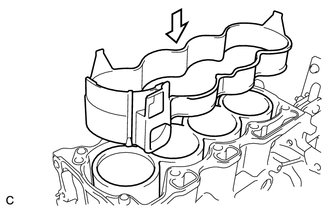
Install the cylinder block water jacket spacer to the cylinder block sub-assembly as shown in the illustration.
-
INSTALL CYLINDER HEAD GASKET
INSTALL CYLINDER HEAD SUB-ASSEMBLY
INSTALL VALVE LASH ADJUSTER ASSEMBLY
Tip: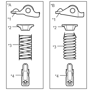
*A
Type A
*B
Type B
*1
No. 1 Valve Rocker Arm Sub-assembly
*2
Valve Spring Retainer
*3
Compression Spring
*4
Valve Lash Adjuster Assembly
Type A and Type B can be distinguished by the shape of the compression spring.
Type
Compression Spring Shape
A
Straight
B
Taper
Type A and Type B:
Note:Keep the valve lash adjuster assembly free of dirt and foreign matter.
Only use clean engine oil.
-
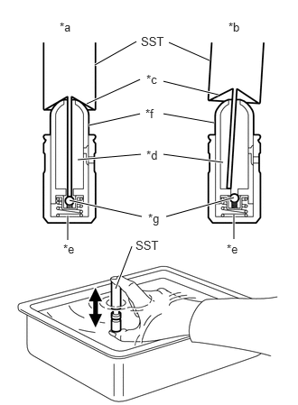
*a
Correct
*b
Incorrect
*c
Taper Part
*d
Low Pressure Chamber
*e
High Pressure Chamber
*f
Plunger
*g
Check Ball
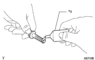
Place the valve lash adjuster assembly into a container filled with engine oil.
Insert the tip of SST into the valve lash adjuster assembly plunger and use the tip to press down on the check ball inside the plunger.
09276-75010
Squeeze SST and the valve lash adjuster assembly together to move the plunger up and down 5 to 6 times.
Check the movement of the plunger and bleed it.
OK
Plunger moves up and down.
Note:When bleeding the high-pressure chamber, make sure that the tip of SST is actually pressing the check ball as shown in the illustration. If the check ball is not pressed, the high-pressure chamber will not be bled.
After bleeding, remove SST. Then, try to press the plunger quickly and firmly by hand.
OK
Plunger is very difficult to move.
If the result is not as specified, replace the valve lash adjuster assembly.
Install the valve lash adjuster assemblies.
Note:Install each valve lash adjuster assembly to the same place it was removed from.
INSTALL NO. 1 VALVE ROCKER ARM SUB-ASSEMBLY
Tip:
*A
Type A
*B
Type B
*1
No. 1 Valve Rocker Arm Sub-assembly
*2
Valve Spring Retainer
*3
Compression Spring
*4
Valve Lash Adjuster Assembly
Type A and Type B can be distinguished by the shape of the compression spring.
Type
Compression Spring Shape
A
Straight
B
Taper
Type A and Type B:
Apply engine oil to the valve lash adjuster assembly tip and valve stem cap end.
-
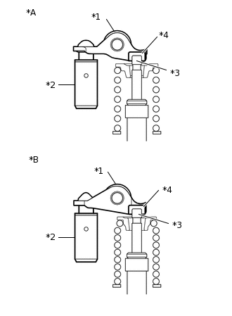
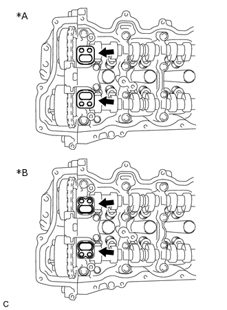
*A
Type A
*B
Type B
*1
No. 1 Valve Rocker Arm sub-assembly
*2
Valve Lash Adjuster assembly
*3
Valve Stem
*4
Valve Stem Cap
Make sure that the No. 1 valve rocker arm sub-assemblies are installed as shown in the illustration.
-
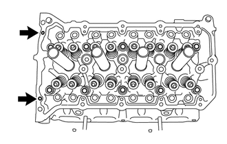
Fill the cylinder head sub-assembly with engine oil through the holes indicated in the illustration.
INSTALL CAMSHAFT
INSTALL NO. 2 CAMSHAFT
INSTALL OIL CONTROL VALVE FILTER
Tip: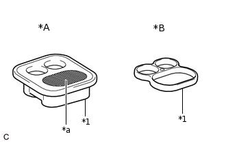
*A
w/ Mesh Type
*B
w/o Mesh Type
*1
Camshaft Bearing Cap Oil Hole Gasket
*a
Mesh
There are 2 types of camshaft bearing cap oil hole gaskets: with mesh and without mesh. For the without mesh type, the oil control valve filter is installed to the camshaft bearing cap.
-
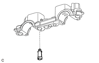
Install the oil control valve filter to the camshaft bearing cap.
-
INSTALL CAMSHAFT BEARING CAP
INSTALL CAMSHAFT HOUSING SUB-ASSEMBLY
INSTALL CAMSHAFT TIMING GEAR ASSEMBLY
INSTALL CAMSHAFT TIMING EXHAUST GEAR ASSEMBLY
INSTALL TIMING CHAIN GUIDE
INSTALL CHAIN SUB-ASSEMBLY
INSTALL TIMING CHAIN TENSION ARM
INSTALL NO. 1 CHAIN TENSIONER ASSEMBLY
INSTALL TIMING CHAIN COVER OIL SEAL
INSTALL TIMING CHAIN COVER SUB-ASSEMBLY
-
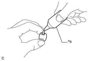
*a
Adhesive
Apply adhesive to 2 or 3 threads of the plug.
Adhesive
Toyota Genuine Adhesive 1324, Three Bond 1324 or equivalent
-
Using an 8 mm socket hexagon wrench, install the plug.
15 N*m
153 kgf*cm
11 ft.*lbf
Note:Install the plug within 3 minutes of applying adhesive.
Do not start the engine within 1 hour after installation.
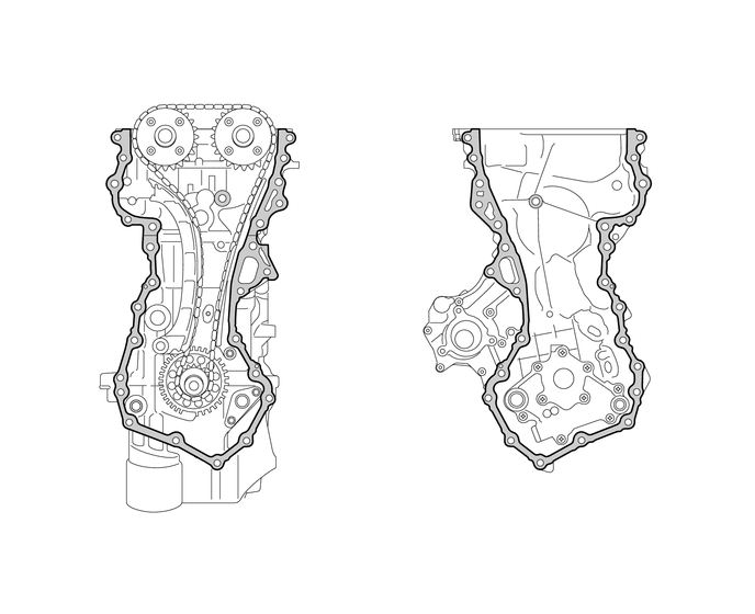
Remove any old seal packing remaining on the sealing surfaces before applying seal packing.
Clean the contact surfaces of the timing chain cover sub-assembly, camshaft housing sub-assembly, cylinder head sub-assembly, cylinder block sub-assembly and oil pan sub-assembly and confirm that no oil, moisture, or other foreign matter is on the surfaces.

Surface to be cleaned
-
-
-
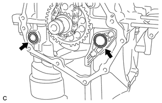
Install 2 new O-rings to the oil pan sub-assembly and oil strainer sub-assembly.
Apply seal packing to the timing chain cover sub-assembly as shown in the following illustration.
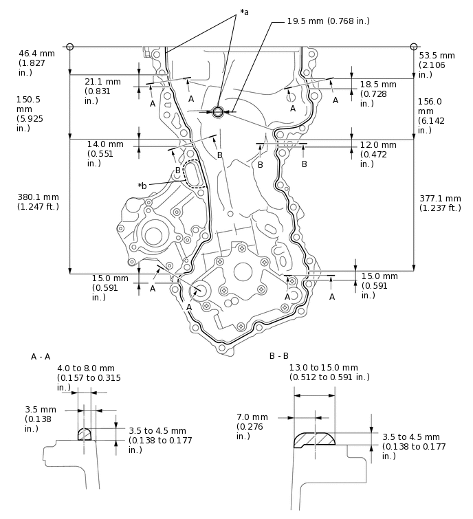
*a
Toyota Genuine Seal Packing Black, Three Bond 1207B or equivalent
*b
Toyota Genuine Seal Packing 1282B, Three Bond 1282B or equivalent
Note:If there is oil on the contact surfaces, wipe them with oil-free cloth before applying seal packing.
Install the timing chain cover sub-assembly within 3 minutes and tighten the bolts within 10 minutes of applying seal packing.
Do not start the engine for at least 2 hours after installation.
Tip:Areas A - A and B - B are the joints between the cylinder block sub-assembly and oil pan sub-assembly, cylinder block sub-assembly and cylinder head sub-assembly, and cylinder head sub-assembly and camshaft housing sub-assembly.
Seal Packing Specification
Area
Seal Packing Diameter
Seal packing
Continuous Line Area
Except A - A and B - B
3.5 to 4.5 mm (0.138 to 0.177 in.)
Toyota Genuine Seal Packing Black, Three Bond 1207B or equivalent
Dashed Line Area
2.0 to 3.0 mm (0.0787 to 0.118 in.)
Toyota Genuine Seal Packing 1282B, Three Bond 1282B or equivalent
Align the oil pump drive rotor and crankshaft as shown in the illustration.
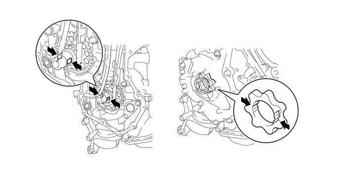
Install the timing chain cover sub-assembly to the crankshaft.
-
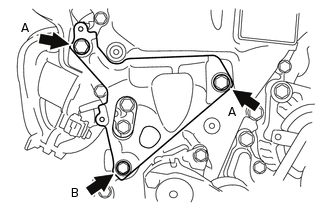
Temporarily install the engine mounting bracket RH with the 3 bolts.
Bolt Length
Item
Length
Bolt A
80 mm (3.150 in.)
Bolt B
40 mm (1.575 in.)
-
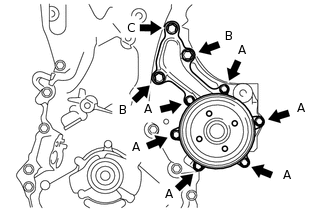
Temporarily install the engine water pump assembly and a new gasket to the timing chain cover sub-assembly with the 9 bolts.
Bolt Length
Item
Length
Bolt A
18 mm (0.709 in.)
Bolt B
40 mm (1.575 in.)
Bolt C
40 mm (1.575 in.) or 50 mm (1.969 in.)
Tighten the 6 bolts (A) shown in the illustration.
Bolt A
9.1 N*m
93 kgf*cm
81 in.*lbf
-
*a
Adhesive
Apply adhesive to the threads of the bolt (E).
Adhesive
Toyota Genuine Adhesive 1324, Three Bond 1324 or equivalent
Tip:Apply adhesive to the bolt (E) more than 7.0 mm (0.276 in.) from the bolt end.
Temporarily tighten the timing chain cover sub-assembly with the 21 bolts and seal washer.
*1
Seal Washer
-
-
Bolt Length
Item
Length
Bolt A
40 mm (1.575 in.) or 50 mm (1.969 in.)
Bolt B
40 mm (1.575 in.)
Bolt C
35 mm (1.378 in.)
Bolt D, E
25 mm (0.984 in.)
Bolt F
80 mm (3.150 in.)
Fully tighten the timing chain cover sub-assembly with the 27 bolts in the order shown in the illustration.
Bolt A, F
71 N*m
724 kgf*cm
52 ft.*lbf
Bolt B, D, E
24 N*m
245 kgf*cm
18 ft.*lbf
Bolt C
10 N*m
102 kgf*cm
7 ft.*lbf
-
INSTALL THERMOSTAT
INSTALL NO. 2 WATER INLET HOUSING GASKET
INSTALL WATER INLET
INSTALL OIL FILTER ELEMENT
INSTALL CRANKSHAFT PULLEY
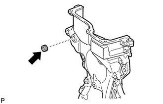
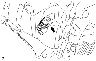
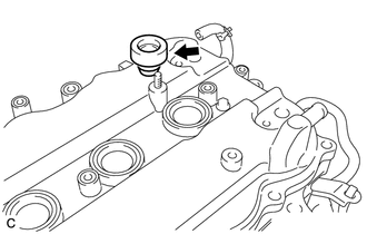
INSTALL ENGINE COOLANT TEMPERATURE SENSOR
-
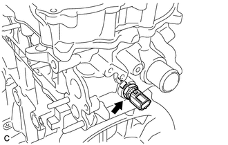
Using a 19 mm deep socket wrench, install a new gasket and engine coolant temperature sensor to the cylinder head sub-assembly.
20 N*m
204 kgf*cm
15 ft.*lbf
Tip:Perform "Inspection After Repair" after replacing the engine coolant temperature sensor.
-
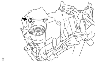
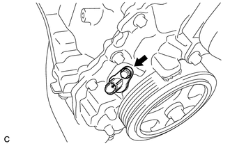
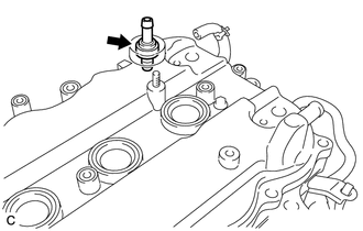
INSTALL KNOCK CONTROL SENSOR
-
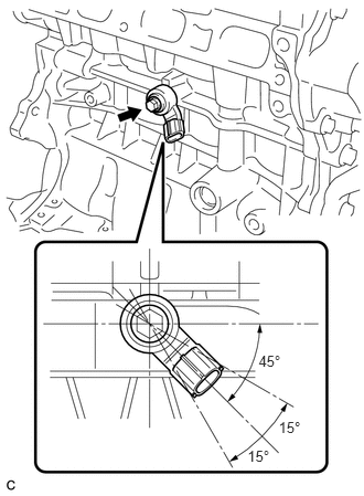
Install the knock control sensor to the cylinder block sub-assembly with the bolt.
20 N*m
204 kgf*cm
15 ft.*lbf
Note:Make sure that the knock control sensor is at the position shown in the illustration.
-
INSTALL ENGINE OIL PRESSURE SWITCH ASSEMBLY
-
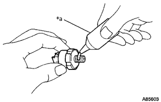
*a
Adhesive
Apply adhesive to 2 or 3 threads of the engine oil pressure switch assembly.
Adhesive
Toyota Genuine Adhesive 1344, Three Bond 1344 or equivalent
-
Using a 24 mm deep socket wrench, install the engine oil pressure switch assembly to the cylinder block sub-assembly.
15 N*m
153 kgf*cm
11 ft.*lbf
Note:Install the engine oil pressure switch assembly within 3 minutes of applying adhesive.
Do not start the engine for at least 1 hour after installation.
-
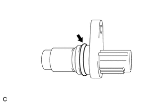
INSTALL CRANK POSITION SENSOR
-
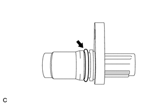
Apply a light coat of engine oil to the O-ring of the crank position sensor.
-
Install the crank position sensor with the bolt.
10 N*m
102 kgf*cm
7 ft.*lbf
-
INSTALL CYLINDER HEAD COVER SUB-ASSEMBLY
Tip:
*A
w/ Mesh Type
*B
w/o Mesh Type
*1
Camshaft Bearing Cap Oil Hole Gasket
*a
Mesh
There are 2 types of camshaft bearing cap oil hole gaskets: with mesh and without mesh. For the without mesh type, the oil control valve filter is installed to the camshaft bearing cap.
-
Install a new cylinder head cover gasket to the cylinder head cover sub-assembly.
Note:Remove any oil from the contact surfaces.
Check that no camshaft bearing cap oil hole gaskets are stuck to the cylinder head cover sub-assembly.
-
*A
w/ Mesh Type
*B
w/o Mesh Type
Install the 2 new camshaft bearing cap oil hole gaskets to the camshaft bearing cap.
Tip:The camshaft bearing cap oil hole gaskets can be installed with either side facing upward. (w/o Mesh Type)
-
*a
Seal Diameter 2.0 mm
Apply seal packing as shown the illustration.
Seal packing
Toyota Genuine Seal Packing Black, Three Bond 1207B or equivalent
Seal diameter
2.0 mm (0.0787 in.)
Note:Remove any oil from the contact surfaces.
Install the cylinder head cover sub-assembly within 3 minutes and tighten the bolts within 15 minutes of applying seal packing.
Do not start the engine for at least 2 hours after the installation.
-
*1
Seal Washer
Apply adhesive to 2 or 3 threads at the end of the bolt (A).
Adhesive
Toyota Genuine Adhesive 1324, Three Bond 1324 or equivalent
Tip:If the removed bolt did not have adhesive applied to it, make sure to apply adhesive to the threads of the bolt before installing it.
If the removed bolt had adhesive applied to it, make sure to clean the bolt and bolt hole and apply adhesive to the threads of the bolt before installing it.
Temporarily install the cylinder head cover sub-assembly with 2 new seal washers and the 17 bolts.
-
Apply a light coat of engine oil to the 2 O-rings of the 2 camshaft position sensors.
Apply adhesive to 2 or 3 threads at the end of the bolt.
Adhesive
Toyota Genuine Adhesive 1324, Three Bond 1324 or equivalent
Tip:If the removed bolt did not have adhesive applied to it, make sure to apply adhesive to the threads of the bolt before installing it.
If the removed bolt had adhesive applied to it, make sure to clean the bolt and bolt hole and apply adhesive to the threads of the bolt before installing it.
-
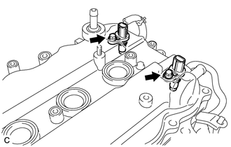
Temporarily install the 2 camshaft position sensors with the 2 bolts.
-
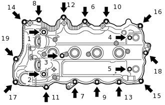
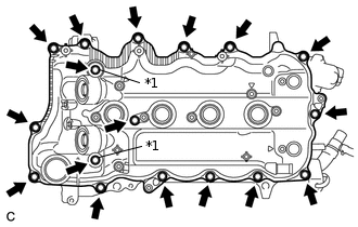
Install the 19 bolts in the order shown in the illustration.
10 N*m
102 kgf*cm
7 ft.*lbf
-
INSTALL CRANKSHAFT BEARING (w/ Stop and Start System)
Visually check the crankshaft bearing installation surface for damage, deformation, or cracks.
If damaged, smooth the surface with 400-grit sandpaper.
-
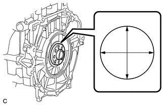
Using a vernier caliper, measure the diameter as shown in the illustration.
Standard diameter
78.045 to 78.064 mm (3.0726 to 3.0734 in.)
If the diameter is not as specified, replace the crankshaft.
Install the snap ring to the crankshaft bearing.
-
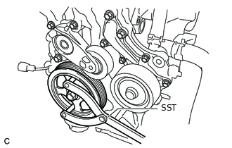
Using SST, hold the crankshaft.
09960-10010
09962-01000
09963-01000
-
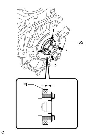
*1
Snap Ring
Using SST, uniformly tighten the 4 bolts in several steps and in the order shown in the illustration to install a new crankshaft bearing to the crankshaft.
09223-47010
Note:Install the crankshaft bearing so that the snap ring faces the front of the engine.
Tighten the bolts until SST contacts the crankshaft.
INSTALL REAR ENGINE OIL SEAL
INSTALL VENTILATION SYSTEM GROMMET
-
Install the ventilation system grommet to the cylinder head cover sub-assembly.
-
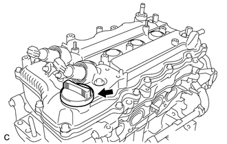
INSTALL VENTILATION VALVE SUB-ASSEMBLY
-
Install the ventilation valve sub-assembly to the cylinder head cover sub-assembly.
-
INSTALL CAMSHAFT TIMING OIL CONTROL VALVE ASSEMBLY
-
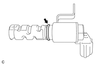
Apply a light coat of engine oil to 2 new O-rings, then install them onto the 2 camshaft timing oil control valve assemblies.
-
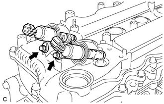
Install the 2 camshaft timing oil control valve assemblies to the cylinder head cover sub-assembly with the 2 bolts.
10 N*m
102 kgf*cm
7 ft.*lbf
-
INSTALL SPARK PLUG
INSTALL OIL FILLER CAP GASKET
-
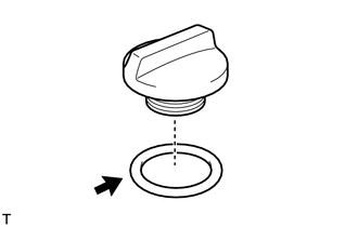
Install the oil filler cap gasket to the oil filler cap sub-assembly.
-
INSTALL OIL FILLER CAP SUB-ASSEMBLY
-
Install the oil filler cap sub-assembly to the cylinder head cover sub-assembly.
-