POWER WINDOW CONTROL SYSTEM TERMINALS OF ECU
CHECK FRONT DOOR WINDOW REGULATOR ASSEMBLY (for Driver Side)

Table 1. Text in Illustration *1
for LHD
*2
for RHD
*1: for LHD
*2: for RHD
Disconnect the K8*1 or J6*2 regulator connector.
Measure the resistance and voltage according to the value(s) in the table below.
Table 2. for LHD Terminal No. (Symbol)
Wiring Color
Terminal Description
Condition
Specified Condition
K8-2 (B) - K8-1 (GND)
L - W-B
Battery power supply
Always
11 to 14 V
K8-1 (GND) - Body ground
W-B - Body ground
Ground
Always
Below 1 Ω
Table 3. for RHD Terminal No. (Symbol)
Wiring Color
Terminal Description
Condition
Specified Condition
J6-2 (B) - J6-1 (GND)
L - W-B
Battery power supply
Always
11 to 14 V
J6-1 (GND) - Body ground
W-B - Body ground
Ground
Always
Below 1 Ω
If the result is not as specified, there may be a malfunction on the wire harness side.
Reconnect the K8*1 or J6*2 regulator connector.
Measure the voltage according to the value(s) in the table below.
Table 4. for LHD Terminal No. (Symbol)
Wiring Color
Terminal Description
Condition
Specified Condition
K8-10 (UP) - K8-1 (GND)
W - W-B
Power window up operation
Ignition switch ON, power window regulator master switch off → up
11 to 14 V → Below 1 V
K8-10 (UP) - K8-1 (GND)
W - W-B
Power window up operation
Ignition switch ON, door glass fully open → power window auto up operation → door glass fully closed
11 to 14 V → Below 1 V → 11 to 14 V
K8-7 (DOWN) - K8-1 (GND)
B - W-B
Power window down operation
Ignition switch ON, power window regulator master switch off → down
11 to 14 V → Below 1 V
K8-7 (DOWN) - K8-1 (GND)
B - W-B
Power window down operation
Ignition switch ON, door glass fully closed → power window auto down operation → door glass fully open
11 to 14 V → Below 1 V → 11 to 14 V
Table 5. for RHD Terminal No. (Symbol)
Wiring Color
Terminal Description
Condition
Specified Condition
J6-10 (UP) - J6-1 (GND)
W - W-B
Power window up operation
Ignition switch ON, power window regulator master switch off → up
11 to 14 V → Below 1 V
J6-10 (UP) - J6-1 (GND)
W - W-B
Power window up operation
Ignition switch ON, door glass fully open → power window auto up operation → door glass fully closed
11 to 14 V → Below 1 V → 11 to 14 V
J6-7 (DOWN) - J6-1 (GND)
B - W-B
Power window down operation
Ignition switch ON, power window regulator master switch off → down
11 to 14 V → Below 1 V
J6-7 (DOWN) - J6-1 (GND)
B - W-B
Power window down operation
Ignition switch ON, door glass fully closed → power window auto down operation → door glass fully open
11 to 14 V → Below 1 V → 11 to 14 V
If the result is not as specified, the regulator may have a malfunction.
CHECK FRONT DOOR WINDOW REGULATOR ASSEMBLY (for Front Passenger Side)

Table 6. Text in Illustration *1
for LHD
*2
for RHD
*1: for LHD
*2: for RHD
Disconnect the J8*1 or K10*2 regulator connector.
Measure the resistance and voltage according to the value(s) in the table below.
Table 7. for LHD Terminal No. (Symbol)
Wiring Color
Terminal Description
Condition
Specified Condition
J8-2 (B) - J8-1 (GND)
G - W-B
Battery power supply
Always
11 to 14 V
J8-1 (GND) - Body ground
W-B - Body ground
Ground
Always
Below 1 Ω
Table 8. for RHD Terminal No. (Symbol)
Wiring Color
Terminal Description
Condition
Specified Condition
K10-2 (B) - K10-1 (GND)
G - W-B
Battery power supply
Always
11 to 14 V
K10-1 (GND) - Body ground
W-B - Body ground
Ground
Always
Below 1 Ω
If the result is not as specified, there may be a malfunction on the wire harness side.
Reconnect the J8*1 or K10*2 regulator connector.
Measure the voltage according to the value(s) in the table below.
Table 9. for LHD Terminal No. (Symbol)
Wiring Color
Terminal Description
Condition
Specified Condition
J8-10 (UP) - J8-1 (GND)
B - W-B
Power window up operation
Ignition switch ON, power window regulator switch off → up
11 to 14 V → Below 1 V
J8-10 (UP) - J8-1 (GND)
B - W-B
Power window up operation
Ignition switch ON, door glass fully open → power window auto up operation → door glass fully closed
11 to 14 V → Below 1 V → 11 to 14 V
J8-7 (DOWN) - J8-1 (GND)
P - W-B
Power window down operation
Ignition switch ON, power window regulator switch off → down
11 to 14 V → Below 1 V
J8-7 (DOWN) - J8-1 (GND)
P - W-B
Power window down operation
Ignition switch ON, door glass fully closed → power window auto down operation → door glass fully open
11 to 14 V → Below 1 V → 11 to 14 V
Table 10. for RHD Terminal No. (Symbol)
Wiring Color
Terminal Description
Condition
Specified Condition
K10-10 (UP) - K10-1 (GND)
B - W-B
Power window up operation
Ignition switch ON, power window regulator switch off → up
11 to 14 V → Below 1 V
K10-10 (UP) - K10-1 (GND)
B - W-B
Power window up operation
Ignition switch ON, door glass fully open → power window auto up operation → door glass fully closed
11 to 14 V → Below 1 V → 11 to 14 V
K10-7 (DOWN) - K10-1 (GND)
P - W-B
Power window down operation
Ignition switch ON, power window regulator switch off → down
11 to 14 V → Below 1 V
K10-7 (DOWN) - K10-1 (GND)
P - W-B
Power window down operation
Ignition switch ON, door glass fully closed → power window auto down operation → door glass fully open
11 to 14 V → Below 1 V → 11 to 14 V
If the result is not as specified, the regulator may have a malfunction.
CHECK REAR DOOR WINDOW REGULATOR ASSEMBLY LH (w/ Rear Door Power Window)

Disconnect the M3 regulator connector.
Measure the resistance and voltage according to the value(s) in the table below.
Terminal No. (Symbol)
Wiring Color
Terminal Description
Condition
Specified Condition
M3-2 (B) - M3-1 (GND)
BR - W-B
Battery power supply
Always
11 to 14 V
M3-1 (GND) - Body ground
W-B - Body ground
Ground
Always
Below 1 Ω
If the result is not as specified, there may be a malfunction on the wire harness side.
Reconnect the M3 regulator connector.
Measure the voltage according to the value(s) in the table below.
Terminal No. (Symbol)
Wiring Color
Terminal Description
Condition
Specified Condition
M3-10 (UP) - M3-1 (GND)
B - W-B
Power window up operation
Ignition switch ON, power window regulator switch off → up
11 to 14 V → Below 1 V
M3-10 (UP) - M3-1 (GND)
B - W-B
Power window up operation
Ignition switch ON, door glass fully open → power window auto up operation → door glass fully closed
11 to 14 V → Below 1 V → 11 to 14 V
M3-7 (DOWN) - M3-1 (GND)
P - W-B
Power window down operation
Ignition switch ON, power window regulator switch off → down
11 to 14 V → Below 1 V
M3-7 (DOWN) - M3-1 (GND)
P - W-B
Power window down operation
Ignition switch ON, door glass fully closed → power window auto down operation → door glass fully open
11 to 14 V → Below 1 V → 11 to 14 V
If the result is not as specified, the regulator may have a malfunction.
CHECK REAR DOOR WINDOW REGULATOR ASSEMBLY RH (w/ Rear Door Power Window)

Disconnect the L3 regulator connector.
Measure the resistance and voltage according to the value(s) in the table below.
Terminal No. (Symbol)
Wiring Color
Terminal Description
Condition
Specified Condition
L3-2 (B) - L3-1 (GND)
L - W-B
Battery power supply
Always
11 to 14 V
L3-1 (GND) - Body ground
W-B - Body ground
Ground
Always
Below 1 Ω
If the result is not as specified, there may be a malfunction on the wire harness side.
Reconnect the L3 regulator connector.
Measure the voltage according to the value(s) in the table below.
Terminal No. (Symbol)
Wiring Color
Terminal Description
Condition
Specified Condition
L3-10 (UP) - L3-1 (GND)
B - W-B
Power window up operation
Ignition switch ON, power window regulator switch off → up
11 to 14 V → Below 1 V
L3-10 (UP) - L3-1 (GND)
B - W-B
Power window up operation
Ignition switch ON, door glass fully open → power window auto up operation → door glass fully closed
11 to 14 V → Below 1 V → 11 to 14 V
L3-7 (DOWN) - L3-1 (GND)
P - W-B
Power window down operation
Ignition switch ON, power window regulator switch off → down
11 to 14 V → Below 1 V
L3-7 (DOWN) - L3-1 (GND)
P - W-B
Power window down operation
Ignition switch ON, door glass fully closed → power window auto down operation → door glass fully open
11 to 14 V → Below 1 V → 11 to 14 V
If the result is not as specified, the regulator may have a malfunction.
CHECK POWER WINDOW REGULATOR MASTER SWITCH ASSEMBLY

Table 11. Text in Illustration *1
for LHD
*2
for RHD
*1: for LHD
*2: for RHD
Disconnect the K5*1 or J5*2 master switch connector.
Measure the resistance and voltage according to the value(s) in the table below.
Table 12. for LHD Terminal No. (Symbol)
Wiring Color
Terminal Description
Condition
Specified Condition
K5-11 (B) - K5-12 (GND)
R - W-B
Battery power supply
Always
11 to 14 V
K5-12 (GND) - Body ground
W-B - Body ground
Ground
Always
Below 1 Ω
Table 13. for RHD Terminal No. (Symbol)
Wiring Color
Terminal Description
Condition
Specified Condition
J5-11 (B) - J5-12 (GND)
R - W-B
Battery power supply
Always
11 to 14 V
J5-12 (GND) - Body ground
W-B - Body ground
Ground
Always
Below 1 Ω
If the result is not as specified, there may be a malfunction on the wire harness side.
Reconnect the K5*1 or J5*2 master switch connector.
Measure the voltage according to the value(s) in the table below.
Table 14. for LHD Terminal No. (Symbol)
Wiring Color
Terminal Description
Condition
Specified Condition
K5-20 (UP) - K5-12 (GND)
W - W-B
Power window up operation
Ignition switch ON, power window regulator master switch off → up
11 to 14 V → Below 1 V
K5-20 (UP) - K5-12 (GND)
W - W-B
Power window up operation
Ignition switch ON, door glass fully open → power window auto up operation → door glass fully closed
11 to 14 V → Below 1 V → 11 to 14 V
K5-15 (DOWN) - K5-12 (GND)
B - W-B
Power window down operation
Ignition switch ON, power window regulator master switch off → down
11 to 14 V → Below 1 V
K5-15 (DOWN) - K5-12 (GND)
B - W-B
Power window down operation
Ignition switch ON, door glass fully closed → power window auto down operation → door glass fully open
11 to 14 V → Below 1 V → 11 to 14 V
Table 15. for RHD Terminal No. (Symbol)
Wiring Color
Terminal Description
Condition
Specified Condition
J5-20 (UP) - J5-12 (GND)
W - W-B
Power window up operation
Ignition switch ON, power window regulator master switch off → up
11 to 14 V → Below 1 V
J5-20 (UP) - J5-12 (GND)
W - W-B
Power window up operation
Ignition switch ON, door glass fully open → power window auto up operation → door glass fully closed
11 to 14 V → Below 1 V → 11 to 14 V
J5-15 (DOWN) - J5-12 (GND)
B - W-B
Power window down operation
Ignition switch ON, power window regulator master switch off → down
11 to 14 V → Below 1 V
J5-15 (DOWN) - J5-12 (GND)
B - W-B
Power window down operation
Ignition switch ON, door glass fully closed → power window auto down operation → door glass fully open
11 to 14 V → Below 1 V → 11 to 14 V
If the result is not as specified, the master switch may have a malfunction.
CHECK POWER WINDOW REGULATOR SWITCH ASSEMBLY

Table 16. Text in Illustration *1
for LHD
*2
for RHD
*1: for LHD
*2: for RHD
Disconnect the J4*1 or K4*2 switch connector.
Measure the resistance according to the value(s) in the table below.
Table 17. for LHD Terminal No. (Symbol)
Wiring Color
Terminal Description
Condition
Specified Condition
J4-1 (GND) - Body ground
W-B - Body ground
Ground
Always
Below 1 Ω
Table 18. for RHD Terminal No. (Symbol)
Wiring Color
Terminal Description
Condition
Specified Condition
K4-1 (GND) - Body ground
W-B - Body ground
Ground
Always
Below 1 Ω
If the result is not as specified, there may be a malfunction on the wire harness side.
Reconnect the J4*1 or K4*2 switch connector.
Measure the voltage according to the value(s) in the table below.
Table 19. for LHD Terminal No. (Symbol)
Wiring Color
Terminal Description
Condition
Specified Condition
J4-6 (UP) - J4-1 (GND)
B - W-B
Power window up operation
Ignition switch ON, power window regulator switch off → up
11 to 14 V → Below 1 V
J4-7 (DOWN) - J4-1 (GND)
P - W-B
Power window down operation
Ignition switch ON, power window regulator switch off → down
11 to 14 V → Below 1 V
J4-8 (AUTO) - J4-1 (GND)
W - W-B
Power window up operation
Ignition switch ON, door glass fully open → power window auto up operation → door glass fully closed
11 to 14 V → Below 1 V → 11 to 14 V
J4-8 (AUTO) - J4-1 (GND)
W - W-B
Power window down operation
Ignition switch ON, door glass fully closed → power window auto down operation → door glass fully open
11 to 14 V → Below 1 V → 11 to 14 V
Table 20. for RHD Terminal No. (Symbol)
Wiring Color
Terminal Description
Condition
Specified Condition
K4-6 (UP) - K4-1 (GND)
B - W-B
Power window up operation
Ignition switch ON, power window regulator switch off → up
11 to 14 V → Below 1 V
K4-7 (DOWN) - K4-1 (GND)
P - W-B
Power window down operation
Ignition switch ON, power window regulator switch off → down
11 to 14 V → Below 1 V
K4-8 (AUTO) - K4-1 (GND)
W - W-B
Power window up operation
Ignition switch ON, door glass fully open → power window auto up operation → door glass fully closed
11 to 14 V → Below 1 V → 11 to 14 V
K4-8 (AUTO) - K4-1 (GND)
W - W-B
Power window down operation
Ignition switch ON, door glass fully closed → power window auto down operation → door glass fully open
11 to 14 V → Below 1 V → 11 to 14 V
If the result is not as specified, the switch may have a malfunction.
CHECK REAR POWER WINDOW REGULATOR SWITCH ASSEMBLY LH (w/ Rear Door Power Window)

Disconnect the M1 switch connector.
Measure the resistance according to the value(s) in the table below.
Terminal No. (Symbol)
Wiring Color
Terminal Description
Condition
Specified Condition
M1-1 (GND) - Body ground
W-B - Body ground
Ground
Always
Below 1 Ω
If the result is not as specified, there may be a malfunction on the wire harness side.
Reconnect the M1 switch connector.
Measure the voltage according to the value(s) in the table below.
Terminal No. (Symbol)
Wiring Color
Terminal Description
Condition
Specified Condition
M1-6 (UP) - M1-1 (GND)
B - W-B
Power window up operation
Ignition switch ON, power window regulator switch off → up
11 to 14 V → Below 1 V
M1-7 (DOWN) - M1-1 (GND)
P - W-B
Power window down operation
Ignition switch ON, power window regulator switch off → down
11 to 14 V → Below 1 V
M1-8 (AUTO) - M1-1 (GND)
W - W-B
Power window up operation
Ignition switch ON, door glass fully open → power window auto up operation → door glass fully closed
11 to 14 V → Below 1 V → 11 to 14 V
M1-8 (AUTO) - M1-1 (GND)
W - W-B
Power window down operation
Ignition switch ON, door glass fully closed → power window auto down operation → door glass fully open
11 to 14 V → Below 1 V → 11 to 14 V
If the result is not as specified, the switch may have a malfunction.
CHECK REAR POWER WINDOW REGULATOR SWITCH ASSEMBLY RH (w/ Rear Door Power Window)

Disconnect the L1 switch connector.
Measure the resistance according to the value(s) in the table below.
Terminal No. (Symbol)
Wiring Color
Terminal Description
Condition
Specified Condition
L1-1 (GND) - Body ground
W-B - Body ground
Ground
Always
Below 1 Ω
If the result is not as specified, there may be a malfunction on the wire harness side.
Reconnect the L1 switch connector.
Measure the voltage according to the value(s) in the table below.
Terminal No. (Symbol)
Wiring Color
Terminal Description
Condition
Specified Condition
L1-6 (UP) - L1-1 (GND)
B - W-B
Power window up operation
Ignition switch ON, power window regulator switch off → up
11 to 14 V → Below 1 V
L1-7 (DOWN) - L1-1 (GND)
P - W-B
Power window down operation
Ignition switch ON, power window regulator switch off → down
11 to 14 V → Below 1 V
L1-8 (AUTO) - L1-1 (GND)
W - W-B
Power window up operation
Ignition switch ON, door glass fully open → power window auto up operation → door glass fully closed
11 to 14 V → Below 1 V → 11 to 14 V
L1-8 (AUTO) - L1-1 (GND)
W - W-B
Power window down operation
Ignition switch ON, door glass fully closed → power window auto down operation → door glass fully open
11 to 14 V → Below 1 V → 11 to 14 V
If the result is not as specified, the switch may have a malfunction.
CHECK MAIN BODY ECU (INSTRUMENT PANEL JUNCTION BLOCK ASSEMBLY)
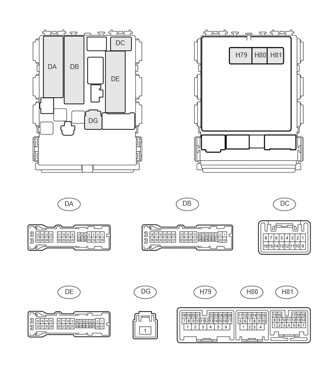
Disconnect the DB, DE, DG and H80 ECU connectors.
Measure the resistance and voltage according to the value(s) in the table below.
Terminal No. (Symbol)
Wiring Color
Terminal Description
Condition
Specified Condition
DE-28 (GND1) - Body ground
W-B - Body ground
Ground
Always
Below 1 Ω
H80-4 (GND2) - Body ground
W-B - Body ground
Ground
Always
Below 1 Ω
DH-12 (BECU) - Body ground
B - Body ground
Power source
Always
11 to 14 V
DG-1 (ALTB) - Body ground
W - Body ground
If the result is not as specified, there may be a malfunction on the wire harness side.
Reconnect the DB, DE, DG and H80 ECU connectors.
Measure the voltage according to the value(s) in the table below.
Table 21. for LHD Terminal No. (Symbol)
Wiring Color
Terminal Description
Condition
Specified Condition
DA-21 (DCTY) - Body ground
W - Body ground
Front door courtesy light switch LH input
Driver side door open
Below 1 V
Driver side door closed
11 to 14 V
DE-20 (PCTY) - Body ground
BR - Body ground
Front door courtesy light switch RH input
Front passenger side door open
Below 1 V
Front passenger side door closed
11 to 14 V
Table 22. for RHD Terminal No. (Symbol)
Wiring Color
Terminal Description
Condition
Specified Condition
DC-6 (DCTY) - Body ground
BR - Body ground
Front door courtesy light switch RH input
Driver side door open
Below 1 V
Driver side door closed
11 to 14 V
DA-24 (PCTY) - Body ground
W - Body ground
Front door courtesy light switch LH input
Front passenger side door open
Below 1 V
Front passenger side door closed
11 to 14 V
If the result is not as specified, the ECU may have a malfunction.