BRAKE ACTUATOR INSTALLATION
PROCEDURE
INSTALL BRAKE ACTUATOR ASSEMBLY
for Type A Brake Actuator Assembly:
-
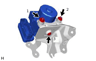
Install the brake actuator assembly to the brake actuator bracket assembly with the bolt and 2 new nuts.
Bolt
5.4 N*m
55 kgf*cm
48 in.*lbf
Nut
7.5 N*m
76 kgf*cm
66 in.*lbf
Note:Do not remove the hole plugs of a new brake actuator assembly before connecting the brake lines because the brake actuator assembly is filled with brake fluid.
Do not hold the brake actuator assembly by the connector.
Tighten the bolt and 2 nuts in the order shown in the illustration.
-
for Type B Brake Actuator Assembly:
-
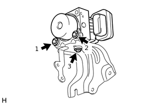
Install the brake actuator assembly to the brake actuator bracket assembly with the 3 bolts.
5.4 N*m
55 kgf*cm
48 in.*lbf
Note:Do not remove the hole plugs of a new brake actuator assembly before connecting the brake lines because the brake actuator assembly is filled with brake fluid.
Do not hold the brake actuator assembly by the connector.
Tighten the 3 bolts in the order shown in the illustration.
-
INSTALL BRAKE ACTUATOR WITH BRACKET
for Type A Brake Actuator Assembly:
-
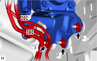
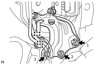
Install the brake actuator with bracket to the vehicle body with 3 new nuts.
19 N*m
194 kgf*cm
14 ft.*lbf
Note:Do not damage the brake lines, fuel lines or wire harness.
Tighten the 3 nuts in the order shown in the illustration.
Engage each clamp to install the No. 2 fuel tube clamp and front No. 4 brake tube to the brake actuator bracket assembly.
Note:Do not damage the brake lines or fuel lines.
-
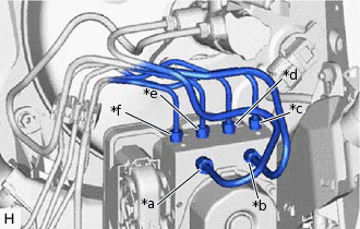
*a
for LHD:
From 1st Chamber of Master Cylinder Sub-assembly
for RHD:
From 2nd Chamber of Master Cylinder Sub-assembly
*b
for LHD:
From 2nd Chamber of Master Cylinder Sub-assembly
for RHD:
From 1st Chamber of Master Cylinder Sub-assembly
*c
To Front Wheel Cylinder Assembly RH
*d
To Rear Wheel Cylinder Assembly LH
*e
To Rear Wheel Cylinder Assembly RH
*f
To Front Wheel Cylinder Assembly LH
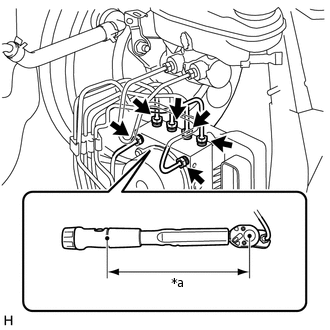
Temporarily tighten each brake line to the correct position on the brake actuator assembly as shown in the illustration.
-
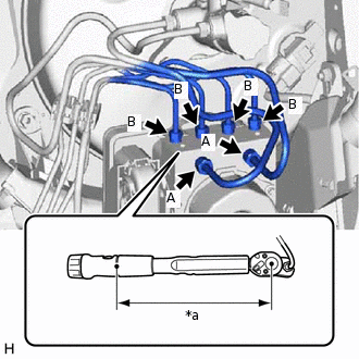
*a
Torque Wrench Fulcrum Length
Using a union nut wrench, fully tighten each brake line.
Specified tightening torque (A) (w/o VSC)
15.2 N*m
155 kgf*cm
11 ft.*lbf
Specified tightening torque (A) (w/ VSC)
19.5 N*m
199 kgf*cm
14 ft.*lbf
Specified tightening torque (B)
15.2 N*m
155 kgf*cm
11 ft.*lbf
Tip:Calculate the torque wrench reading when changing the fulcrum length of the torque wrench.
When using a union nut wrench (fulcrum length of 20 mm (0.787 in.)) + torque wrench (fulcrum length of 162 mm (6.38 in.)):
w/ VSC (A): 17.36 N*m (177 kgf*cm, 13 ft.*lbf)
When using a union nut wrench (fulcrum length of 22 mm (0.866 in.)) + torque wrench (fulcrum length of 162 mm (6.38 in.)):
w/o VSC (A), (B): 13.38 N*m (136 kgf*cm, 10 ft.*lbf)
-
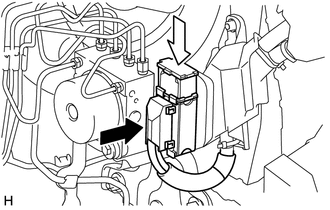
Engage the clamp to install the wire harness to the brake actuator bracket assembly.
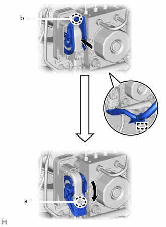
Connect the connector to the brake actuator assembly and disengage the claw (b).
Pull the lever down and engage the claw (a) to engage the connector lock.
Note:Make sure that the connector is locked securely.
Make sure that the actuator connector can be connected smoothly. Do not allow water, oil or dirt to enter the connector.
-
for Type B Brake Actuator Assembly:
-
Install the brake actuator with bracket to the vehicle body with the 3 nuts.
19 N*m
194 kgf*cm
14 ft.*lbf
Note:Do not damage the brake lines, fuel lines or wire harness.
Tighten the 3 nuts in the order shown in the illustration.
Engage each clamp to install the No. 2 fuel tube clamp and front No. 4 brake tube to the brake actuator bracket assembly.
Note:Do not damage the brake lines or fuel lines.
-
*a
From 1st Chamber of Master Cylinder Sub-assembly
*b
From 2nd Chamber of Master Cylinder Sub-assembly
*c
To Front Wheel Cylinder Assembly LH
*d
To Rear Wheel Cylinder Assembly RH
*e
To Rear Wheel Cylinder Assembly LH
*f
To Front Wheel Cylinder Assembly RH
Temporarily tighten each brake line to the correct position on the brake actuator assembly as shown in the illustration.
-
*a
Torque Wrench Fulcrum Length
Using a union nut wrench, fully tighten each brake line.
Specified tightening torque
15.2 N*m
155 kgf*cm
11 ft.*lbf
Tip:Calculate the torque wrench reading when changing the fulcrum length of the torque wrench.
When using a union nut wrench (fulcrum length of 22 mm (0.866 in.)) + torque wrench (fulcrum length of 162 mm (6.38 in.)):
13.38 N*m (136 kgf*cm, 10 ft.*lbf)
-

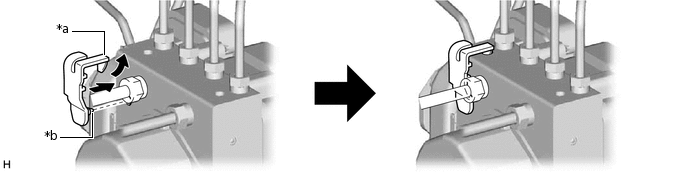
Connect

Lock
Connect the connector to the brake actuator assembly and lock the lock lever.
Note:Make sure that the connector is locked securely.
Make sure that the actuator connector can be connected smoothly. Do not allow water, oil or dirt to enter the connector.
-
Connect the connector to the ECM.
for 1NR-FE:Click here
for 1ZR-FE:Click here
for 1ZR-FAE:Click here
for 2ZR-FE:Click here
for 8NR-FTS:Click here
INSTALL BRAKE ACTUATOR COVER (for 1WW, 1ND-TV with VSC)
Raise the claw of a new brake actuator cover, insert the pin into the hole and engage the claw to install it to the brake actuator assembly.
*a
Claw
*b
Pin
INSTALL AIR CLEANER BRACKET (for 1WW, 1ND-TV)
Install the air cleaner bracket with the 3 bolts.
7.0 N*m
71 kgf*cm
62 in.*lbf
INSTALL FUEL FILTER SUPPORT (for 1WW, 1ND-TV)
Install the fuel filter support with the 3 bolts.
17.5 N*m
178 kgf*cm
13 ft.*lbf
Engage the wire harness clamp to the fuel filter support.
INSTALL GLOW PLUG RELAY ASSEMBLY (for 1WW, 1ND-TV)
Install the glow plug relay assembly to the fuel filter support with the bolt.
for 1ND-TV
11 N*m
112 kgf*cm
8 ft.*lbf
for 1WW
17.5 N*m
178 kgf*cm
13 ft.*lbf
Connect the wire harness clamp to the fuel filter support.
CONNECT WIRE HARNESS (for 1ND-TV)
Connect the ECM connector to the ECM.
w/o Glow Plug Controller:Click here
w/ Glow Plug Controller:Click here
Connect the 3 wire harness clamps to the fuel filter support.
CONNECT WIRE HARNESS (for 1WW)
Connect the ECM connector to the ECM.
Connect the 2 wire harness clamps to the fuel filter support.
Connect the connector.
INSTALL FUEL FILTER ASSEMBLY (for 1WW, 1ND-TV)
for 1WW:Click here
for 1ND-TV:Click here
INSTALL NO. 1 FUEL FILTER PROTECTOR (for 1WW)
INSTALL AIR CLEANER CASE SUB-ASSEMBLY (for 1NR-FE)
INSTALL AIR CLEANER CAP SUB-ASSEMBLY (for 1NR-FE)
INSTALL NO. 1 ENGINE COVER (for 1NR-FE)
INSTALL AIR CLEANER CASE SUB-ASSEMBLY (for 1ZR-FE)
INSTALL AIR CLEANER CAP SUB-ASSEMBLY (for 1ZR-FE)
INSTALL NO. 2 CYLINDER HEAD COVER (for 1ZR-FE)
INSTALL AIR CLEANER CASE SUB-ASSEMBLY (for 1ZR-FAE)
INSTALL AIR CLEANER CAP SUB-ASSEMBLY (for 1ZR-FAE)
INSTALL NO. 2 CYLINDER HEAD COVER (for 1ZR-FAE)
INSTALL AIR CLEANER CASE SUB-ASSEMBLY (for 2ZR-FE)
INSTALL AIR CLEANER CAP SUB-ASSEMBLY (for 2ZR-FE)
INSTALL NO. 2 CYLINDER HEAD COVER (for 2ZR-FE)
INSTALL AIR CLEANER CASE SUB-ASSEMBLY (for 1ND-TV)
w/o Glow Plug Controller:Click here
w/ Glow Plug Controller:Click here
INSTALL AIR CLEANER CAP SUB-ASSEMBLY (for 1ND-TV)
w/o Glow Plug Controller:Click here
w/ Glow Plug Controller:Click here
INSTALL NO. 1 ENGINE COVER (for 1ND-TV with No. 1 Engine Cover)
w/o Glow Plug Controller:Click here
w/ Glow Plug Controller:Click here
INSTALL AIR CLEANER CASE SUB-ASSEMBLY (for 8NR-FTS)
INSTALL AIR CLEANER CAP WITH AIR CLEANER HOSE (for 8NR-FTS)
INSTALL AIR CLEANER CASE SUB-ASSEMBLY (for 1WW)
INSTALL AIR CLEANER CAP SUB-ASSEMBLY WITH AIR CLEANER HOSE ASSEMBLY (for 1WW)
INSTALL NO. 1 ENGINE COVER (for 1WW)
CONNECT CABLE TO NEGATIVE BATTERY TERMINAL
Note:When disconnecting the cable, some systems need to be initialized after the cable is reconnected.
BLEED AIR FROM FUEL SYSTEM (for 1ND-TV)
CHECK FUEL PUMP OPERATION AND INSPECT FOR FUEL LEAK (for 1WW)
INSPECT FOR FUEL LEAK (for 1ND-TV)
w/o Glow Plug Controller:Click here
w/ Glow Plug Controller:Click here
BLEED BRAKE SYSTEM
INSPECT BRAKE ACTUATOR USING GTS
PERFORM SYSTEM VARIANT LEARNING (w/ VSC)
CHECK FOR AND CLEAR DTCS