ECD SYSTEM (w/o EGR Cooler) VC Output Circuit
DESCRIPTION
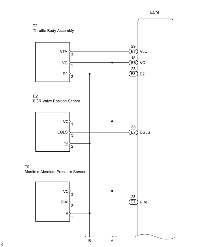
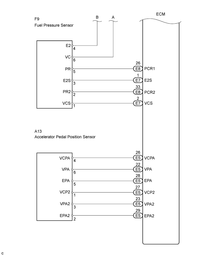
The VC voltage (5 V) is generated in the ECM. The voltage is used to supply power to the throttle body assembly, EGR valve position sensor, turbo pressure sensor, accelerator position sensor and fuel pressure sensor.
WIRING DIAGRAM
INSPECTION PROCEDURE
Note
After replacing the ECM, the new ECM needs registration Click here and initialization Click here.
PROCEDURE
-
CHECK MIL
-
Check that the Malfunction Indicator Lamp (MIL) lights up when turning the ignition switch ON.
OK MIL lights up
OK 
SYSTEM OK
NG 
-
-
CHECK CONNECTION BETWEEN INTELLIGENT TESTER AND ECM
-
Connect the intelligent tester to the DLC3.
-
Turn the ignition switch ON and tester ON.
-
Check the communication between the intelligent tester and ECM.
Result Condition Proceed to Communication is not possible A Communication is possible B
B
GO TO MIL CIRCUIT Click here
A
-
-
CHECK ECM (VC VOLTAGE)
-
Turn the ignition switch ON.
-
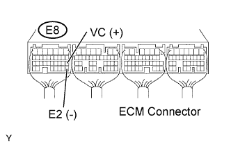
Measure the voltage of the ECM connector.
Result Tester Connection Specified Condition VC (E8-18) - E2 (E8-28) Voltage is not 5 V
NEXT
-
-
CHECK MIL (THROTTLE POSITION SENSOR)
-
Disconnect the T2 throttle position sensor connector.
-
Turn the ignition switch ON.
-
Check the MIL.
Result Condition Proceed to MIL does not illuminate A MIL illuminates B -
Reconnect the throttle position sensor connector.
B
REPLACE DIESEL THROTTLE BODY ASSEMBLY Click here
A
-
-
CHECK MIL (MANIFOLD ABSOLUTE PRESSURE SENSOR)
-
Disconnect the T9 manifold absolute pressure sensor connector.
-
Turn the ignition switch ON.
-
Check the MIL.
Result Condition Proceed to MIL does not illuminate A MIL illuminates B -
Reconnect the manifold absolute pressure sensor connector.
B
REPLACE MANIFOLD ABSOLUTE PRESSURE SENSOR
A
-
-
CHECK MIL (ACCELERATOR PEDAL POSITION SENSOR)
-
Disconnect the A13 accelerator pedal position sensor connector.
-
Turn the ignition switch ON.
-
Check the MIL.
Result Condition Proceed to MIL does not illuminate A MIL illuminates B -
Reconnect the accelerator position sensor connector.
B
REPLACE ACCELERATOR PEDAL ROD ASSEMBLY Click here
A
-
-
CHECK MIL (EGR VALVE POSITION SENSOR)
-
Disconnect the E2 EGR valve position sensor connector.
-
Turn the ignition switch ON.
-
Check the MIL.
Result Condition Proceed to MIL does not illuminate A MIL illuminates B -
Disconnect the EGR valve position sensor connector.
B
REPLACE EGR VALVE ASSEMBLY Click here
A
-
-
CHECK MIL (FUEL PRESSURE SENSOR)
-
Disconnect the F9 fuel pressure sensor connector.
-
Turn the ignition switch ON.
-
Check the MIL.
Result Condition Proceed to MIL does not illuminate A MIL illuminates B -
Reconnect the fuel pressure sensor connector.
B
REPLACE COMMON RAIL ASSEMBLY Click here
A
-
-
CHECK HARNESS AND CONNECTOR (ECM - BODY GROUND)
-
Disconnect the T2 throttle position sensor connector.
-
Disconnect the T9 manifold absolute pressure sensor connector.
-
Disconnect the F9 fuel pressure sensor connector.
-
Disconnect the E2 EGR valve position sensor connector.
-
Disconnect the A13 accelerator pedal position sensor connector.
-
Disconnect the E5, E7 and E8 ECM connectors.
-
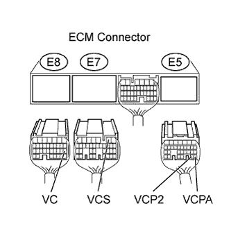
Measure the resistance of the wire harness connector.
Standard resistance (Check for short) Tester Connection Specified Condition VC (E8-18) - Body ground 10 kΩ or higher VCS (E7-2) - Body ground VCPA (E5-26) - Body ground VCP2 (E5-27) - Body ground -
Reconnect the throttle position sensor connector.
-
Reconnect the manifold absolute pressure sensor connector.
-
Reconnect the fuel pressure sensor connector.
-
Reconnect the EGR valve position sensor connector.
-
Reconnect the accelerator pedal position sensor connector.
-
Reconnect the ECM connector.
NG
REPAIR OR REPLACE HARNESS OR CONNECTOR
OK 
REPLACE ECM Click here
-