ROOF HEADLINING REASSEMBLY

CAUTION / NOTICE / HINT
Tech Tips
-
Use the same procedure for RHD and LHD vehicles.
-
The procedure listed below is for LHD vehicles.
-
Use the same procedure for the RH and LH sides.
-
The procedure listed below is for the LH side.
PROCEDURE
-
INSTALL NO. 1 ROOF WIRE
-
for Sliding Roof:
-
Apply butyl tape to the roof headlining ensuring it does not go over the marking.
Tech Tips
-
Apply securely so that the butyl tape will not shift or peel off.
-
The double portion of the butyl tape is set as a surplus absorbing area.
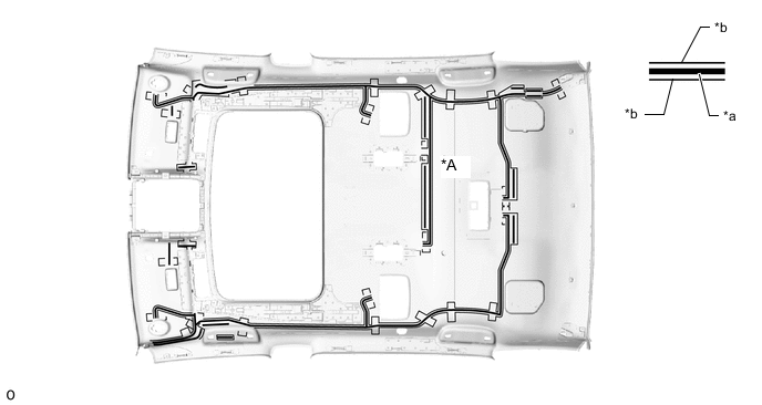
*A for 24 Speakers - - *a Butyl Tape *b Marking -
-
-
for Panoramic Moon Roof:
-
Apply butyl tape to the roof headlining ensuring it does not go over the marking.
Tech Tips
-
Apply securely so that the butyl tape will not shift or peel off.
-
The double portion of the butyl tape is set as a surplus absorbing area.
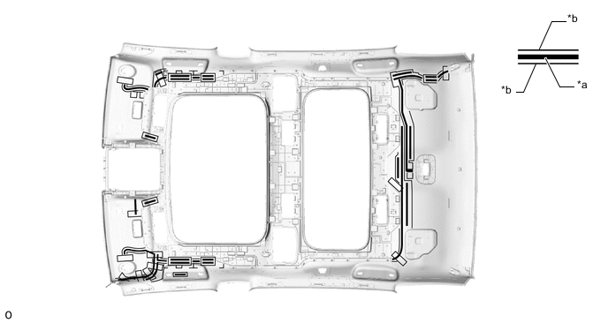
*a Butyl Tape *b Marking -
-
-
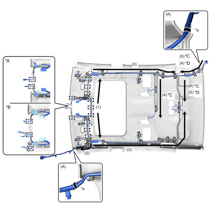
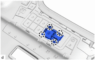
for LHD, Sliding Roof:
-
Attach the No. 1 roof wire to the butyl tape in the order and direction indicated by the arrows shown in the illustration and secure the No. 1 roof wire with pieces of tape.
Tech Tips
-
Align the positioning tape of the No. 1 roof wire with the protrusion of the roof headlining and wrap tape around them as shown in the part of the illustration labeled A.
-
Make sure that the No. 1 roof wire is securely attached to the roof headlining along its entire length and not twisted.
-
-
Attach each guide and each clamp.
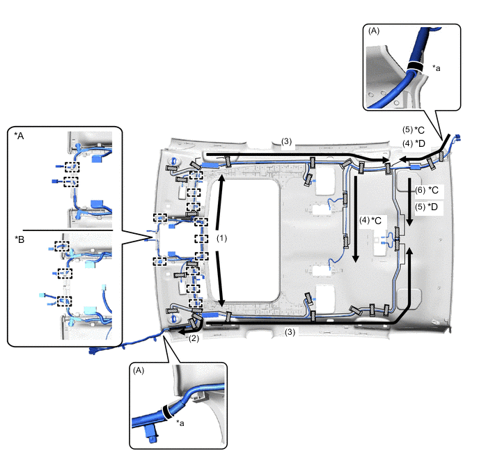
*A w/o Pre-collision *B w/ Pre-collision *C for 24 Speakers *D for 12 Speakers *a Align positioning tape of No. 1 roof wire and protrusion of roof headlining - - 
Tape 
Positioning Tape
-
-
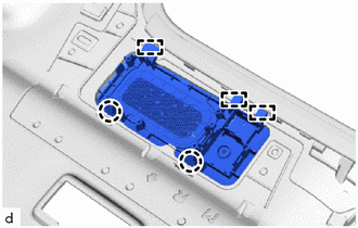
for LHD, Panoramic Moon Roof:
-
Attach the No. 1 roof wire to the butyl tape in the order and direction indicated by the arrows shown in the illustration and secure the No. 1 roof wire with pieces of tape.
Tech Tips
-
Align the positioning tape of the No. 1 roof wire with the protrusion of the roof headlining and wrap tape around them as shown in the part of the illustration labeled A.
-
Make sure that the No. 1 roof wire is securely attached to the roof headlining along its entire length and not twisted.
-
-
Attach each guide and each clamp.
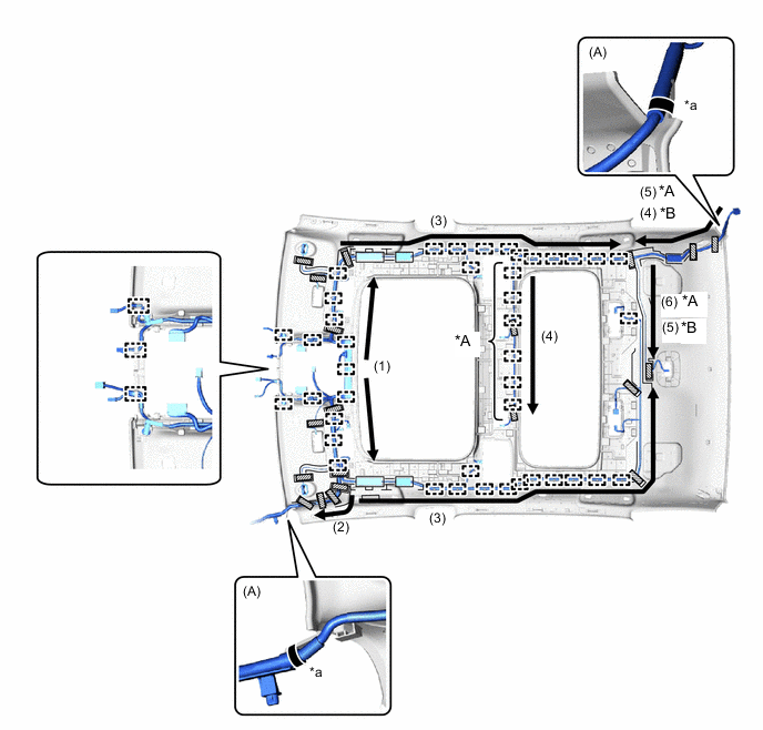
*A for 24 Speakers *B for 12 Speakers *a Align positioning tape of No. 1 roof wire and protrusion of roof headlining - - Tape Positioning Tape
-
-
for RHD:
-
Attach the No. 1 roof wire to the butyl tape in the order and direction indicated by the arrows shown in the illustration and secure the No. 1 roof wire with pieces of tape.
Tech Tips
-
Align the positioning tape of the No. 1 roof wire with the protrusion of the roof headlining and wrap tape around them as shown in the part of the illustration labeled A.
-
Make sure that the No. 1 roof wire is securely attached to the roof headlining along its entire length and not twisted.
-
-
Attach each guide and each clamp.
*A w/o Pre-collision *B w/ Pre-collision *C for 24 Speakers *D for 12 Speakers *a Align positioning tape of No. 1 roof wire and protrusion of roof headlining - - Tape Positioning Tape
-
-
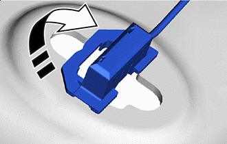

Install in this Direction Turn the visor connectors approximately 90° clockwise and install them to the roof headlining.
-
-
INSTALL ROOF SIDE REGISTER BEZEL LH (w/ Rear Cooler)
-
Insert the guide and attach the claw to install the roof side register bezel LH.
-
-
INSTALL ROOF SIDE REGISTER BEZEL RH (w/ Rear Cooler)
Tech Tips
Use the same procedure described for the LH side.
-
INSTALL REAR SPEAKER GRILLE (for 24 Speakers, Rear Side)
-
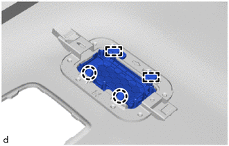
Align the guide and attach the claw to install the rear speaker grille.
Tech Tips
Use the same procedure for the opposite side.
-
-
INSTALL ROOF SPEAKER ASSEMBLY (for 24 Speakers, Rear Side)
-
INSTALL REAR MICROPHONE CASE (for Panoramic Moon Roof)
-
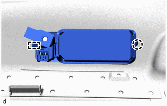
Attach the claw and install the rear microphone case.
-
-
INSTALL ACTIVE NOISE CONTROL MICROPHONE (for Panoramic Moon Roof, Rear Side)
-
INSTALL MICROPHONE CASE LH (for 12 Speakers)
-
Attach the claw and install the microphone case LH.
-
-
INSTALL MICROPHONE CASE RH (for 12 Speakers)
Tech Tips
Use the same procedure described for the LH side.
-
INSTALL ROOF SPEAKER GRILLE LH (for 24 Speakers)
-
Insert the guide and attach the claw to install the roof speaker grille LH.
-
-
INSTALL ROOF SPEAKER GRILLE RH (for 24 Speakers)
Tech Tips
Use the same procedure described for the LH side.
-
INSTALL ACTIVE NOISE CONTROL MICROPHONE (for Front Side)
-
INSTALL TELEPHONE MICROPHONE ASSEMBLY (for Sliding Roof)
-
INSTALL TELEPHONE MICROPHONE ASSEMBLY (for Panoramic Moon Roof)
-
INSTALL ROOF SPEAKER ASSEMBLY (for 24 Speakers, Front Side)