ENGINE UNIT
-
CONSTRUCTION
-
The camshafts are made of cast iron alloy.
-
An oil passage is provided in the intake camshaft (camshaft) and exhaust camshaft (No. 2 camshaft) in order to supply engine oil to the VVT-iW and VVT-i systems.
-
A VVT-i controller (camshaft timing gear assembly or camshaft timing exhaust gear assembly) is installed on the front of the intake camshaft (camshaft) and exhaust camshaft (No. 2 camshaft) to vary the timing of the intake and exhaust valves.
-
Together with the use of the No. 1 valve rocker arm sub-assemblies, the cam profile is modified. This results in increased valve lift when the valve begins to open and as it finishes closing, helping to achieve enhanced output performance.
-
A timing rotor for the camshaft position sensor is provided on the back of the intake camshaft (camshaft) and exhaust camshaft (No. 2 camshaft). Additionally, a cam for powering the fuel pump is installed on the intake camshaft, thus reducing the size of the engine.
-
The cam that drives the fuel pump assembly (for high pressure) is positioned directly above the No. 4 cylinder of the intake camshaft (camshaft) to achieve size reduction. Also, a pump cam with 4 peaks is used in the cam that drives the fuel pump assembly (for high pressure) and by synchronizing fuel pressure-feeding and fuel injection, the difference in fuel pressure between cylinders is reduced.
-
The vacuum pump assembly is driven by the end of the exhaust camshaft (No. 2 camshaft).
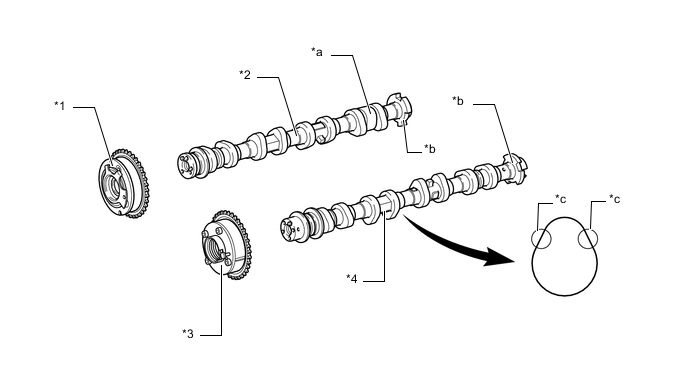
*1 Camshaft Timing Gear Assembly *2 Intake Camshaft (Camshaft) *3 Camshaft Timing Exhaust Gear Assembly *4 Exhaust Camshaft (No. 2 Camshaft) *a Cam (for Powering the Fuel Pump) *b Timing Rotor *c Modified Portion of Cam Profile - -
-