POWER BACK DOOR SYSTEM Power Back Door cannot be Operated Using Kick Sensor
| DTC Code | DTC Name |
|---|---|
| Power Back Door cannot be Operated Using Kick Sensor |
DESCRIPTION
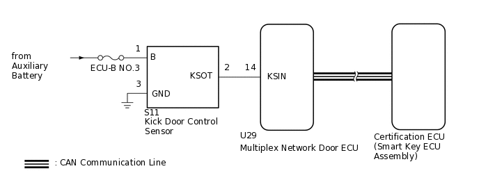
Signals from the kick door control sensor are sent to the multiplex network door ECU. If the power back door system does not operate, there may be a malfunction in the kick door control sensor circuit.
WIRING DIAGRAM
CAUTION / NOTICE / HINT
Before troubleshooting, make sure that the "Kick Sensor Function" customize setting is set to "ON".
Before troubleshooting, be sure to read Precautions for Touchless Power Back Door.
If the multiplex network door ECU has been removed and installed or replaced, or if any of the connectors has been disconnected, initialize the power back door system.
After performing work, using the GTS, read the Data List item "Kick Sensor Connection" and check that the kick door control sensor is connected.
PROCEDURE
CHECK FOR DTC
Check for DTCs.
Body Electrical > Back Door > Trouble Codes
Result
Result
Proceed to
DTC is not output
A
DTC is output
B
READ VALUE USING GTS
Read the Data List according to the display on the GTS.
Body Electrical > Back Door > Data List
Tester Display
Measurement Item
Range
Normal Condition
Diagnostic Note
Kick Sensor Error
Status of the kick door control sensor error
Normal or Error
Normal: Kick door control sensor is normal
Error: Kick door control sensor is abnormal
-
Body Electrical > Back Door > Data List
Tester Display
Kick Sensor Error
OK
On the GTS, Normal is displayed.
Result
Proceed to
OK
NG
READ VALUE USING GTS
Read the Data List according to the display on the GTS.
Body Electrical > Back Door > Data List
Tester Display
Measurement Item
Range
Normal Condition
Diagnostic Note
Kick Sensor Detection
Status of the kick door control sensor detection
OFF or ON
OFF: Kick door control sensor not detecting a foot
ON: Kick door control sensor detecting a foot
-
Body Electrical > Back Door > Data List
Tester Display
Kick Sensor Detection
OK
On GTS screen, item changes between ON and OFF according to above chart.
Result
Proceed to
OK
NG
CHECK HARNESS AND CONNECTOR (KICK DOOR CONTROL SENSOR - BATTERY AND BODY GROUND)
-
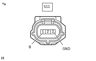
*a
Front view of wire harness connector
(to Kick Door Control Sensor)
Disconnect the kick door control sensor connector.
Measure the resistance according to the value(s) in the table below.
Standard Resistance
Tester Connection
Condition
Specified Condition
S11-3 (GND) - Body ground
Always
Below 1 Ω
Measure the voltage according to the value(s) in the table below.
Standard Voltage
Tester Connection
Condition
Specified Condition
S11-1 (B) - Body ground
Always
11 to 14 V
Result
Proceed to
OK
NG
NG REPAIR OR REPLACE HARNESS OR CONNECTOR
-
CHECK HARNESS AND CONNECTOR (KICK DOOR CONTROL SENSOR - MULTIPLEX NETWORK DOOR ECU)
Disconnect the S11 kick door control sensor connector.
Disconnect the U29 multiplex network door ECU connector.
Measure the resistance according to the value(s) in the table below.
Standard Resistance
Tester Connection
Condition
Specified Condition
S11-2 (KSOT) - U29-14 (KSIN)
Always
Below 1 Ω
S11-2 (KSOT) or U29-14 (KSIN) - Body ground
Always
10 kΩ or higher
Result
Proceed to
OK
NG
NG REPAIR OR REPLACE HARNESS OR CONNECTOR
CHECK MULTIPLEX NETWORK DOOR ECU
Remove the multiplex network door ECU with the connector(s) still connected.
-
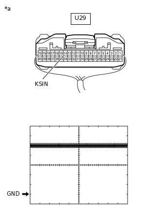
*a
Component with harness connected
(Multiplex Network Door ECU)
Check the signal waveform according to the condition(s) in the table below.
Table 1. Measurement Condition Item
Condition
Tester Connection
U29-14 (KSIN) - Body ground
Tool Setting
2 V/DIV., 50 ms./DIV.
Vehicle Condition
Kick door control sensor not detecting a foot
OK
The waveform displayed is as shown in the illustration.
Result
Proceed to
OK
NG