FUEL MAIN VALVE(w/ Canister Pump Module) REMOVAL
CAUTION / NOTICE / HINT
The necessary procedures (adjustment, calibration, initialization or registration) that must be performed after parts are removed and installed, or replaced during fuel main valve assembly removal/installation are shown below.
| Replaced Part or Performed Procedure | Necessary Procedure | Effect/Inoperative Function when Necessary Procedure not Performed | Link |
|---|---|---|---|
| Battery terminal is disconnected/reconnected | Perform steering sensor zero point calibration | Lane departure alert system (w/ Steering Control) | |
| Pre-collision system | |||
| Memorize steering angle neutral point | Parking assist monitor system | ||
| Replacement of fuel pump | Inspection after repair |
|
CAUTION:
-
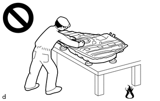
Never perform work on fuel system components near any possible ignition sources.
-
Vaporized fuel could ignite, resulting in a serious accident.
-
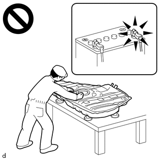
Do not perform work on fuel system components without first disconnecting the cable from the negative (-) battery terminal.
-
Sparks could cause vaporized fuel to ignite, resulting in a serious accident.
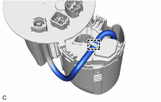
Note
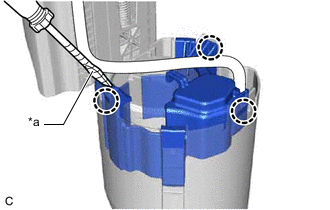
-
Do not disconnect the tube shown in the illustration when disassembling the fuel suction tube with pump and gauge assembly. Doing so will cause reassembly of the fuel suction tube with pump and gauge assembly to be impossible as the tube is pressed into the fuel suction plate sub-assembly.
-
When replacing the fuel filter, replace it together with the fuel suction plate sub-assembly.
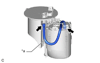
| *a | Tube |
PROCEDURE
-
REMOVE FUEL SUCTION TUBE WITH PUMP AND GAUGE ASSEMBLY
-
REMOVE FUEL SENDER GAUGE ASSEMBLY
-
SEPARATE FUEL FILTER
-
Disengage the clamp to disconnect the tube from the fuel filter.
-
*a Protective Tape Using a screwdriver with its tip wrapped with protective tape, disengage the 3 claws.
-
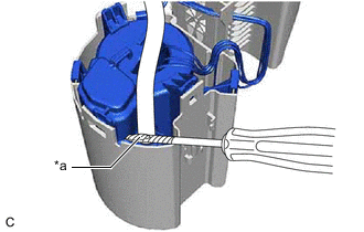
*a Protective Tape Using a screwdriver with its tip wrapped with protective tape, separate the fuel filter from the fuel sub-tank.
Note
-
Do not damage the fuel sub-tank and fuel filter.
-
Pull out the fuel filter carefully because the O-ring is firmly installed between the fuel filter and fuel sub-tank.
-
Do not do anything which may separate the tube from either the fuel suction plate sub-assembly or fuel filter, such as applying excessive force to the tube.
-
-
Remove the O-ring from the fuel sub-tank.
-
-
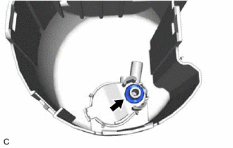
REMOVE FUEL MAIN VALVE ASSEMBLY (for Low Pressure)
-
Remove the clip from the fuel filter.
-
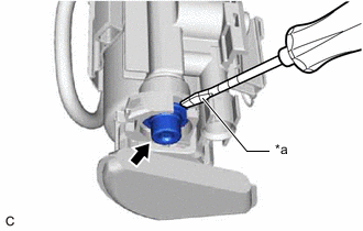
*a Protective Tape Using a screwdriver with its tip wrapped with protective tape, remove the fuel main valve assembly from the fuel filter.
Note
-
Pull out the fuel main valve assembly carefully because the O-rings are firmly installed between the fuel main valve assembly and fuel filter.
-
Do not damage the fuel filter.
-
-
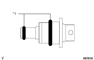
*1 O-ring Remove the 2 O-rings from the fuel main valve assembly.
-
-
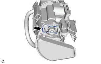
REMOVE FUEL MAIN VALVE ASSEMBLY (for High Pressure)
-
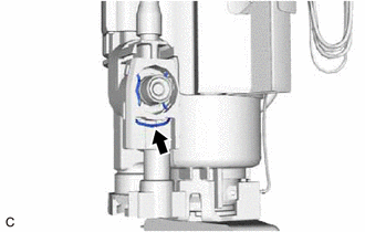
Remove the clip from the fuel filter.
-
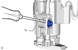
*a Protective Tape Using a screwdriver with its tip wrapped with protective tape, remove the fuel main valve assembly from the fuel filter.
Note
-
Pull out the fuel main valve assembly carefully because the O-rings are firmly installed between the fuel main valve assembly and fuel filter.
-
Do not damage the fuel filter.
-
-
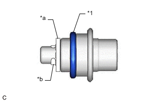
*1 O-ring *a Mesh *b Mini-clip Remove the O-ring from the fuel main valve assembly.
Note
Do not remove the mesh and mini-clip from the fuel main valve assembly.
-