MULTI-MODE MANUAL TRANSAXLE SYSTEM, Diagnostic DTC:P0703
| DTC Code | DTC Name |
|---|---|
| P0703 | Brake Switch "B" Circuit |
DESCRIPTION
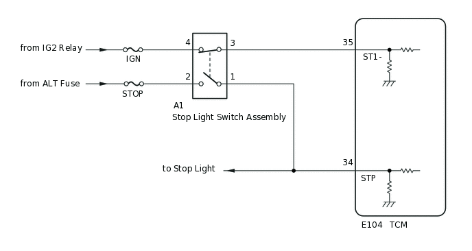
When the brake pedal is depressed, stop light switch signal STP turns on and stop light switch signal ST1- turns off. The TCM detects whether the brake pedal is depressed or released based on those signals. If the signal conditions, STP and ST1-, do not match the standard condition, the TCM interprets this as a malfunction in the stop light switch circuit and stores this DTC.
DTC No. |
Detection Item |
DTC Detection Condition |
Trouble Area |
MIL |
Warning Indicate |
Memory |
|---|---|---|---|---|---|---|
P0703 |
Brake Switch "B" Circuit |
Following conditions detected simultaneously for 1.0 second or more (1-trip detection logic)
|
|
Does not come on |
Comes on |
DTC stored |
WIRING DIAGRAM
CAUTION / NOTICE / HINT
Inspect the fuses for circuits related to this system before performing the following procedure.
PROCEDURE
READ VALUE USING GTS (BRAKE SWITCH SIGNAL 1 AND 2)
Connect the GTS to the DLC3.
Turn the ignition switch to ON.
Turn the GTS on.
Enter the following menus: Powertrain / Multi-Mode M/T / Data List / Brake Switch Signal1 and Brake Switch Signal2.
According to the display on the GTS, read the Data List.
Powertrain > Multi-Mode M/T > Data List
Tester Display
Measurement Item
Range
Normal Condition
Diagnostic Note
Brake Switch Signal2
Brake switch signal (ST1-)
OFF or ON
OFF: Brake pedal depressed
ON: Brake pedal released
ST1- terminal signal of TCM
Brake Switch Signal1
Brake switch signal (STP)
OFF or ON
OFF: Brake pedal released
ON: Brake pedal depressed
STP terminal signal of TCM
Powertrain > Multi-Mode M/T > Data List
Tester Display
Brake Switch Signal2
Brake Switch Signal1
OK
The normal conditions listed above are shown on the GTS when the brake pedal is operated.
Result
Proceed to
OK
NG
INSPECT STOP LIGHT SWITCH
Inspect the stop light switch assembly.
Result
Proceed to
OK
NG
CHECK HARNESS AND CONNECTOR (BATTERY - STOP LIGHT SWITCH)
Measure the voltage according to the value(s) in the table below.
Standard Voltage
Tester Connection
Condition
Specified Condition
A1-2 - Body ground
Always
11 to 14 V
A1-4 - Body ground
Ignition switch ON
11 to 14 V
Result
Proceed to
OK
NG
NG REPAIR OR REPLACE HARNESS OR CONNECTOR
CHECK HARNESS AND CONNECTOR (STOP LIGHT SWITCH - TCM)
-
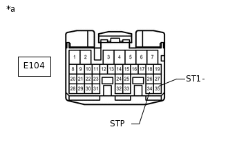
*a
Front view of wire harness connector
(to TCM)
Reconnect the stop light switch connector.
Disconnect the TCM connector.
Turn the ignition switch to ON.
Measure the voltage according to the value(s) in the table below.
Standard Voltage
Tester Connection
Condition
Specified Condition
E104-34 (STP) - Body ground
Brake pedal depressed
11 to 14 V
Brake pedal released
Below 1 V
E104-35 (ST1-) - Body ground
Brake pedal depressed
Below 1 V
Brake pedal released
11 to 14 V
Result
Proceed to
OK
NG
NG REPAIR OR REPLACE HARNESS OR CONNECTOR
-
REPLACE TCM
Replace the TCM.
Result
Proceed to
NEXT
PERFORM INITIALIZATION
Perform the initialization and learning procedure.
Result
Proceed to
NEXT
NEXT END