NAVIGATION SYSTEM Steering Pad Switch Circuit
| DTC Code | DTC Name |
|---|---|
| Steering Pad Switch Circuit |
DESCRIPTION
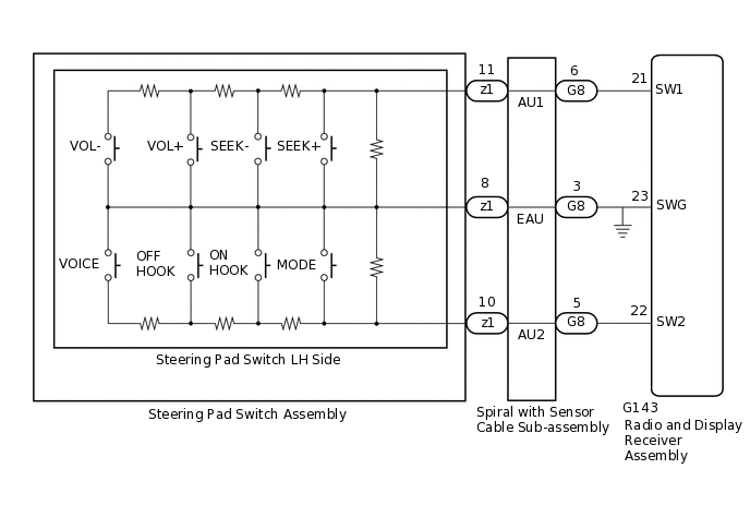
This circuit sends an operation signal from the steering pad switch assembly to the radio and display receiver assembly.
If there is an open in the circuit, the audio system cannot be operated using the steering pad switch assembly.
If there is a short in the circuit, the same condition as when a switch is continuously depressed occurs.
Therefore, the radio and display receiver assembly cannot be operated using the steering pad switch assembly, and also the radio and display receiver assembly itself cannot function.
WIRING DIAGRAM
CAUTION / NOTICE / HINT
The vehicle is equipped with a Supplemental Restraint System (SRS) which includes components such as airbags. Before servicing (including removal or installation of parts), be sure to read the precaution for Supplemental Restraint System.
Check that the wire harness is properly installed and does not have any sharp bends, pinching or loose connections.
PROCEDURE
INSPECT STEERING PAD SWITCH ASSEMBLY
Remove the steering pad switch assembly.
Inspect the steering pad switch assembly.
Result
Proceed to
OK
NG
INSPECT SPIRAL WITH SENSOR CABLE SUB-ASSEMBLY
Remove the spiral with sensor cable sub-assembly.
Inspect the spiral with sensor cable sub-assembly.
Result
Proceed to
OK
NG
CHECK HARNESS AND CONNECTOR (RADIO AND DISPLAY RECEIVER ASSEMBLY - SPIRAL WITH SENSOR CABLE SUB-ASSEMBLY)
Disconnect the G143 radio and display receiver assembly connector.
Disconnect the G8 spiral with sensor cable sub-assembly connector.
Measure the resistance according to the value(s) in the table below.
Standard Resistance
Tester Connection
Condition
Specified Condition
G143-21 (SW1) - G8-6 (AU1)
Always
Below 1 Ω
G143-22 (SW2) - G8-5 (AU2)
Always
Below 1 Ω
G143-23 (SWG) - G8-3 (EAU)
Always
Below 1 Ω
G143-21 (SW1) - Body ground
Always
10 kΩ or higher
G143-22 (SW2) - Body ground
Always
10 kΩ or higher
Result
Proceed to
OK
NG
NG REPAIR OR REPLACE HARNESS OR CONNECTOR