TAIL GATE REASSEMBLY
Tech Tips
A bolt without a torque specification is shown in the standard bolt chart Click here.
-
INSTALL TAIL GATE HINGE ASSEMBLY LH
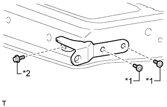
Text in Illustration *1 "TORX" Bolt *2 Bolt
-
Install the tail gate hinge with the bolt.
- Torque:
- 18 N*m { 184 kgf*cm, 13 ft.*lbf }
-
Using a T40 "TORX" socket wrench, install the 2 "TORX" bolts.
- Torque:
- 28 N*m { 286 kgf*cm, 21 ft.*lbf }
-
-
INSTALL TAIL GATE HINGE ASSEMBLY RH
Tech Tips
Use the same procedure described for the LH side.
-
INSTALL TAIL GATE STAY STOPPER (for A Deck)
Tech Tips
Use the same procedure for both tail gate stay stoppers.
-
Install the tail gate stay stopper with the bolt.
-
-
INSTALL TAIL GATE LOCK ASSEMBLY LH (for A Deck)
-
Install the tail gate lock with the 2 bolts.
- Torque:
- 13 N*m { 127 kgf*cm, 9 ft.*lbf }
-
-
INSTALL TAIL GATE LOCK ASSEMBLY RH (for A Deck)
Tech Tips
Use the same procedure described for the LH side.
-
INSTALL TAIL GATE HANDLE ASSEMBLY (for A Deck)
-
Install the tail gate handle with the 2 bolts.
- Torque:
- 5.0 N*m { 51 kgf*cm, 44 in.*lbf }
-
-
INSTALL TAIL GATE LOCK CONTROL LINK LH (for A Deck)
-

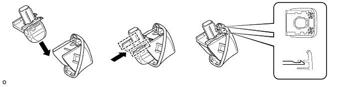
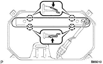
Text in Illustration *1 Snap Install the tail gate lock control link.
-
Rotate the control link snaps in the directions indicated by the arrows in the illustration and attach the control link snaps to the tail gate lock control link.
-
-
INSTALL TAIL GATE LOCK CONTROL LINK RH (for A Deck)
Tech Tips
Use the same procedure described for the LH side.
-
INSTALL REAR BODY TAIL GATE LATCH ASSEMBLY (for J Deck)
Tech Tips
Use the same procedure for both rear body tail gate latches.
-
Install the rear body tail gate latch with the 2 bolts.
- Torque:
- 5.0 N*m { 51 kgf*cm, 44 in.*lbf }
-
-
INSTALL REAR TELEVISION CAMERA ASSEMBLY (w/ Rear View Monitor System)
-
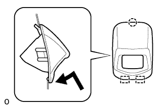
Attach the 2 guides as shown in the illustration.
Tech Tips
Make sure that each guide is attached to its corresponding rail.
-
Attach the 2 claws to install the rear television camera assembly.
Note
Visually check that the guides and claws are attached to the back door No. 2 outside garnish.
-
-
INSTALL NO. 2 BACK DOOR GARNISH OUTSIDE (w/ Rear View Monitor System)
-
Attach the claw and 2 guides as shown in the illustration.
-
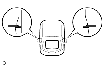
Attach the 2 claws to install the back door No. 2 outside garnish.
-
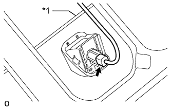
Text in Illustration *1 Tail Gate Lock Control Link Connect the connector.
Note
Make sure that the wire harness is between the tail gate inner panel and tail gate lock control link.
-
-
INSTALL CENTER STOP LIGHT ASSEMBLY (w/ Center Stop Light)
-
Attach the center stop light with the 4 claws.
-
Connect the connector.
-
-
INSTALL TAIL GATE SERVICE HOLE COVER
-
for A Deck:
Install the tail gate service hole cover with the 10 screws.
-
for J Deck:
Install the tail gate service hole cover with the 8 screws.
-