FUEL INJECTOR(w/o Glow Plug Controller) REMOVAL
CAUTION / NOTICE / HINT
When replacing the injector assemblies (including exchanging the injector assemblies between the cylinders), common rail assembly, intake manifold or cylinder head, it is necessary to replace the injection pipe sub-assemblies with new ones.
After replacing any of the injector assemblies, perform both the "Injector Compensation" and the "Pilot Quantity Learning Values Reset" functions using the GTS.
PROCEDURE
REMOVE EGR WITH COOLER PIPE SUB-ASSEMBLY
REMOVE NO. 1 EGR COOLER BRACKET
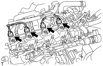
REMOVE NO. 1 INJECTION PIPE SUB-ASSEMBLY
Note:After removing the injection pipe sub-assembly, cover the common rail assembly with protective tape to prevent dirt or foreign matter from entering the pipe inlet. Also protect the injector inlets by covering them with protective tape or plastic bags.
-
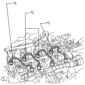
*1
No. 1 Injection Pipe Sub-assembly
*2
No. 2 Injection Pipe Sub-assembly
*3
No. 3 Injection Pipe Sub-assembly
Using a 17 mm union nut wrench, separate the union nut from the injector assembly first, then from the common rail assembly.
Remove the No. 1 injection pipe sub-assembly.
-
REMOVE NO. 2 INJECTION PIPE SUB-ASSEMBLY
Tip:Perform the same procedure as for the No. 1 injection pipe sub-assembly.
REMOVE NO. 3 INJECTION PIPE SUB-ASSEMBLY
Tip:Perform the same procedure as for the No. 1 injection pipe sub-assembly.
REMOVE NO. 1 GLOW PLUG CONNECTOR
-
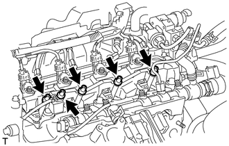
Remove the 5 screw grommets.
-
Remove the nut and disconnect the glow terminal.
Remove the 4 nuts and No. 1 glow plug connector.
-
REMOVE NO. 2 INTAKE MANIFOLD INSULATOR
-
Remove the No. 2 intake manifold insulator.
-
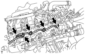
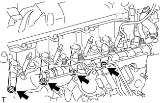
REMOVE NOZZLE LEAKAGE PIPE ASSEMBLY
-
Disconnect the 4 connectors from the 4 injector assemblies.
-
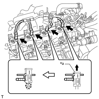
*a
Lock Bush
Pull up the lock bush as shown in the illustration and separate the nozzle leakage pipe assembly.
Note:Do not separate the nozzle leakage pipe assembly by pulling on the hose portion. Separate it while holding onto the lock bush portion.
-
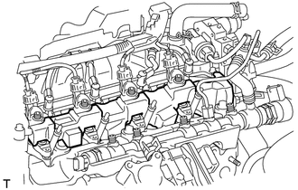
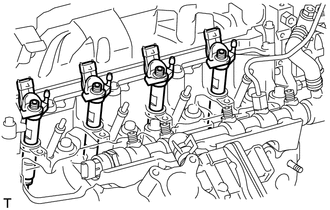
REMOVE NO. 1 NOZZLE HOLDER CLAMP
-
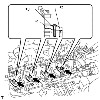
*1
Nozzle Holder Clamp
*2
Nozzle Holder Clamp Seat
*3
Washer
Remove the 4 bolts, 4 washers and 4 nozzle holder clamps.
-
REMOVE NOZZLE HOLDER CLAMP SEAT
-
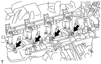
Remove the 4 nozzle holder clamp seats form the cylinder head.
-
REMOVE INJECTOR ASSEMBLY
-
Remove the 4 injector assemblies from the cylinder head.
Note:Each injector assembly has its own fuel injection part number. When replacing the injector assemblies, store them in the correct order so that they can be returned to their original locations when reassembled.
Arrange the injector assemblies, clamps, washers, bolts and clamp seats in the correct order.
-
REMOVE INJECTION NOZZLE SEAT
-
Remove the 4 injection nozzle seats from the injector assemblies or cylinder head.
Note:When removing the injector assembly, check that the injector nozzle seat is either attached to the injector assembly, or remains in the cylinder head.
-