REAR FLOOR SIDE MEMBER CUT AND JOIN REPLACEMENT SECTIONS
-
With the body lower back panel assembly removed.
-
REMOVAL
Symbol Meaning 
Remove Weld Points 
Remove Weld Points 
Cut and Join Location 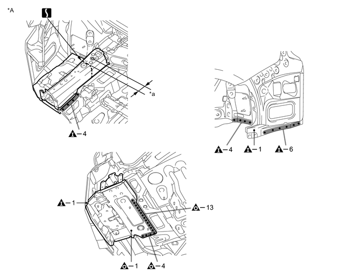
*A LH - - *a 60 mm (2.36 in.) - - 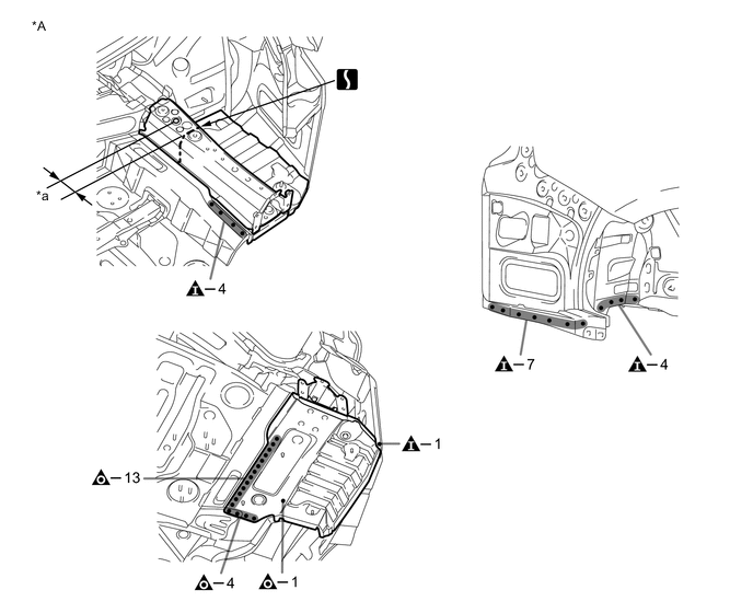
*A RH - - *a 60 mm (2.36 in.) - - -
INSTALLATION
Symbol Meaning 
Plug Weld 
Plug Weld 
Assembly Mark
-
Temporarily install the new parts and measure each part of the new parts in accordance with the body dimension diagram. (See the body dimensions)
-
After welding the rear floor side member reinforcement sub-assembly rear to the vehicle side, install the rear floor side panel sub-assembly.
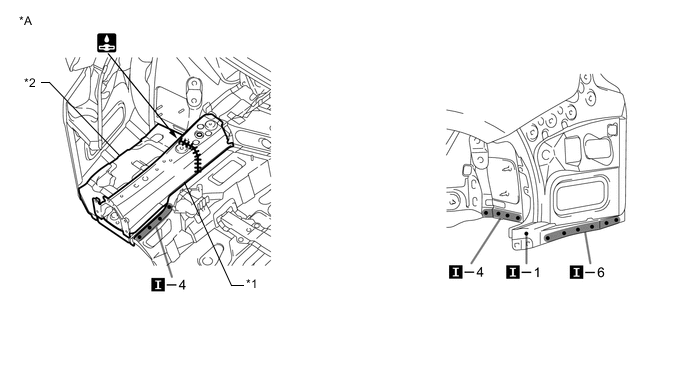
*A LH - - *1 REAR FLOOR SIDE MEMBER REINFORCEMENT SUB-ASSEMBLY REAR *2 REAR FLOOR SIDE PANEL SUB-ASSEMBLY 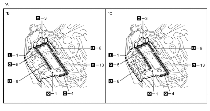
*A LH *B w/o Dynamic Rear Steering *C w/ Dynamic Rear Steering - - -
After welding the rear floor side member reinforcement sub-assembly rear to the vehicle side, install the rear floor side panel sub-assembly.
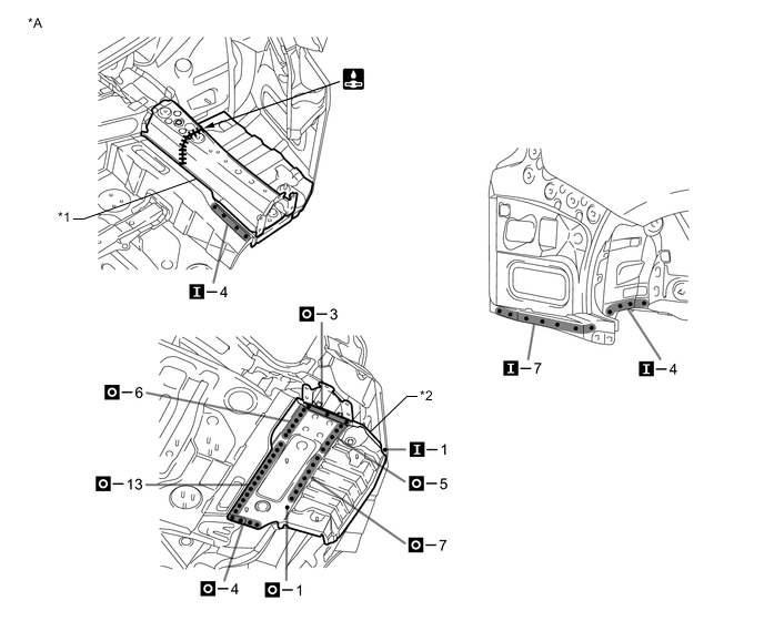
*A RH - - *1 REAR FLOOR SIDE MEMBER REINFORCEMENT SUB-ASSEMBLY REAR *2 REAR FLOOR SIDE PANEL SUB-ASSEMBLY -
After welding, apply body sealer and undercoating to the corresponding parts. (See the painting / coating)
-
After applying the top coat, apply anti-rust agent to the internal panel portion of the closed section structural weld points.
-