METER / GAUGE SYSTEM Headup Display Malfunction
DESCRIPTION
The headup display system displays some vehicle information on the windshield glass.
The headup display system consists of the combination mirror meter ECU and combination meter sub-assembly.
The combination mirror meter ECU receives information from the combination meter sub-assembly via communication and projects it on the windshield.
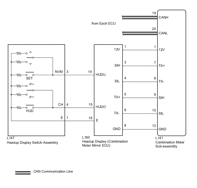
WIRING DIAGRAM
CAUTION / NOTICE / HINT
Tech Tips
Before starting the following inspection, confirm the headup display position and illuminance, then perform the on-vehicle inspection Click here.
PROCEDURE
-
SYSTEM CHECK
-
Check the symptom of the headup display.
Result Result Proceed to Headup display does not display at all. A Display of the headup display is abnormal. B
B 
SYSTEM CHECK Click here
A 
-
-
CHECK HARNESS AND CONNECTOR (COMBINATION METER MIRROR ECU - BODY GROUND)
-
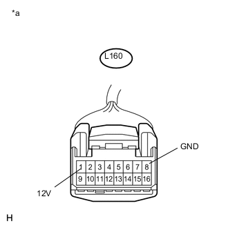
Text in Illustration *a Front view of wire harness connector
(to Combination Meter Mirror ECU)
Disconnect the L160 combination meter mirror ECU connector.
-
Measure the voltage according to the value(s) in the table below.
Standard Voltage Tester Connection Condition Specified Condition L160-1 (12V) - Body ground Power switch on (IG) 11 to 14 V -
Measure the resistance according to the value(s) in the table below
Standard Resistance Tester Connection Condition Specified Condition L160-8 (GND) - Body ground Always Below 1 Ω
NG 
REPAIR OR REPLACE HARNESS OR CONNECTOR
OK
-
-
CHECK HARNESS AND CONNECTOR (COMBINATION METER MIRROR ECU - HEADUP DISPLAY SWITCH ASSEMBLY)
-
Disconnect the L147 headup display switch assembly connector.
-
Measure the resistance according to the value(s) in the table below.
Standard Resistance Tester Connection Condition Specified Condition L160-14 (HUDU) - L147-3 (NVM) Always Below 1 Ω L160-14 (HUDU) - Body ground Always 10 kΩ or higher L160-15 (HUDO) - L147-4 (CH) Always Below 1 Ω L160-15 (HUDO) - Body ground Always 10 kΩ or higher L160-16 (E) - L147-1 (E) Always Below 1 Ω L160-16 (E) - Body ground Always Below 1 Ω
NG
REPAIR OR REPLACE HARNESS OR CONNECTOR
OK
-
-
INSPECT HEADUP DISPLAY SWITCH ASSEMBLY
-
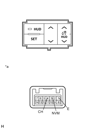
Text in Illustration *a Component without harness connected
(Headup Display Switch Assembly)
Disconnect the L147 headup display switch assembly connector.
-
Measure the resistance according to the value(s) in the table below.
Standard Resistance Tester Connection Switch Condition Specified Condition 3 (NVM) - 1 (E) SET switch is pressed 1782 to 1818 Ω SET switch is not pressed 10 kΩ or higher HUD tilt up switch is pressed 811.8 to 828.2 Ω HUD tilt up switch is not pressed 10 kΩ or higher HUD tilt down switch is pressed 326.7 to 333.3 Ω HUD tilt down switch is not pressed 10 kΩ or higher 4 (CH) - 1 (E) HUD main switch is pressed 1782 to 1818 Ω HUD main switch is not pressed 10 kΩ or higher HUD rheostat up switch is pressed 811.8 to 828.2 Ω HUD rheostat up switch is not pressed 10 kΩ or higher HUD rheostat down switch is pressed 326.7 to 333.3 Ω HUD rheostat down switch is not pressed 10 kΩ or higher
OK
REPLACE COMBINATION METER MIRROR ECU Click here
NG
REPLACE HEADUP DISPLAY SWITCH ASSEMBLY Click here
-
-
SYSTEM CHECK
-
Check the symptom of the headup display.
Result Result Proceed to All display items are abnormal. A Vehicle speed display is abnormal. Dynamic radar cruise control display is abnormal. Pre crash safety system display is abnormal. Touch tracer display is abnormal. Turn-by-turn navigation display is abnormal. B
B
CHECK HARNESS AND CONNECTOR (COMBINATION METER SUB-ASSEMBLY - COMBINATION METER MIRROR ECU) Click here
A
-
-
CHECK HARNESS AND CONNECTOR (COMBINATION METER SUB-ASSEMBLY - COMBINATION METER MIRROR ECU)
-
Disconnect the L141 combination meter sub-assembly connector.
-
Disconnect the L160 combination meter mirror ECU connector.
-
Measure the resistance according to the value(s) in the table below.
Standard Resistance Tester Connection Condition Specified Condition L141-7 (TX+) - L160-3 (SIH) Always Below 1 Ω L141-7 (TX+) - Body ground Always 10 kΩ or higher L141-8 (TX-) - L160-4 (SIL) Always Below 1 Ω L141-8 (TX-) - Body ground Always 10 kΩ or higher L141-9 (SIH) - L160-5 (TX+) Always Below 1 Ω L141-9 (SIH) - Body ground Always 10 kΩ or higher L141-10 (SIL) - L160-6 (TX-) Always Below 1 Ω L141-10 (SIL) - Body ground Always 10 kΩ or higher
NG
REPAIR OR REPLACE HARNESS OR CONNECTOR
OK
-
-
REPLACE COMBINATION METER MIRROR ECU
-
Replace the combination meter mirror ECU with a new or a known good one Click here.
OK The operation of the headup display returns to normal. Result Result Proceed to OK A NG (w/o Multi-information display) B NG (w/ Multi-information display) C
OK
END
B
REPLACE METER CIRCUIT PLATE Click here
C
REPLACE COMBINATION METER SUB-ASSEMBLY Click here
-
-
CHECK HARNESS AND CONNECTOR (COMBINATION METER SUB-ASSEMBLY - COMBINATION METER MIRROR ECU)
-
Disconnect the L141 combination meter sub-assembly connector.
-
Disconnect the L160 combination meter mirror ECU connector.
-
Measure the resistance according to the value(s) in the table below.
Standard Resistance Tester Connection Condition Specified Condition L141-7 (TX+) - L160-3 (SIH) Always Below 1 Ω L141-7 (TX+) - Body ground Always 10 kΩ or higher L141-8 (TX-) - L160-4 (SIL) Always Below 1 Ω L141-8 (TX-) - Body ground Always 10 kΩ or higher L141-9 (SIH) - L160-5 (TX+) Always Below 1 Ω L141-9 (SIH) - Body ground Always 10 kΩ or higher L141-10 (SIL) - L160-6 (TX-) Always Below 1 Ω L141-10 (SIL) - Body ground Always 10 kΩ or higher
NG
REPAIR OR REPLACE HARNESS OR CONNECTOR
OK
-
-
REPLACE COMBINATION METER MIRROR ECU
-
Replace the combination meter mirror ECU with a new or a known good one Click here.
OK The operation of the headup display returns to normal. Result Result Proceed to OK A NG (w/o Multi-information display) B NG (w/ Multi-information display) C
A
END
C
REPLACE COMBINATION METER SUB-ASSEMBLY Click here
B
-
-
REPLACE METER CIRCUIT PLATE
-
Replace the meter circuit plate with a new or a known good one Click here.
OK The operation of the headup display returns to normal.
OK
END
NG
REPLACE NAVIGATION RECEIVER ASSEMBLY Click here
-
-
REPLACE COMBINATION METER SUB-ASSEMBLY
-
Replace the combination meter sub-assembly with a new or a known good one Click here.
OK The operation of the headup display returns to normal.
OK
END
NG
REPLACE NAVIGATION RECEIVER ASSEMBLY Click here
-