ELECTRONICALLY CONTROLLED BRAKE SYSTEM, Diagnostic DTC:C1235/35,C1236/36,C1238/38,C1239/39,C1275/75,C1276/76,C1277/77 and C1278/78
| DTC Code | DTC Name |
|---|---|
| C1235/35 | Foreign Object is Attached on Tip of Front Speed Sensor RH |
| C1236/36 | Foreign Object is Attached on Tip of Front Speed Sensor LH |
| C1238/38 | Foreign Object is Attached on Tip of Rear Speed Sensor RH |
| C1239/39 | Foreign Object is Attached on Tip of Rear Speed Sensor LH |
| C1275/75 | Abnormal Change in Output Signal of Front Speed Sensor RH (Test Mode DTC) |
| C1276/76 | Abnormal Change in Output Signal of Front Speed Sensor LH (Test Mode DTC) |
| C1277/77 | Abnormal Change in Output Signal of Rear Speed Sensor RH (Test Mode DTC) |
| C1278/78 | Abnormal Change in Output Signal of Rear Speed Sensor LH (Test Mode DTC) |
DESCRIPTION
When foreign matter adheres to a speed sensor tip or speed sensor rotor, these DTCs are stored. The presence of foreign matter can be judged when an abnormal waveform is received from a sensor.
These DTCs may also be detected when a malfunction occurs in the connector terminals or wire harness of the speed sensor circuit.
DTCs C1275/75 to C1278/78 will be cleared when the speed sensor sends a wheel speed signal or when Test Mode ends. DTCs from C1275/75 to C1278/78 are output only in Test Mode.
DTC No. |
Detection Item |
INF Code |
DTC Detection Condition |
Trouble Area |
Note |
|---|---|---|---|---|---|
C1235/35 |
Foreign Object is Attached on Tip of Front Speed Sensor RH |
541 |
Either of the following is detected:
|
|
ABS DTC |
C1236/36 |
Foreign Object is Attached on Tip of Front Speed Sensor LH |
542 |
Either of the following is detected:
|
|
ABS DTC |
C1238/38 |
Foreign Object is Attached on Tip of Rear Speed Sensor RH |
543 |
Either of the following is detected:
|
|
ABS DTC |
C1239/39 |
Foreign Object is Attached on Tip of Rear Speed Sensor LH |
544 |
Either of the following is detected:
|
|
ABS DTC |
C1275/75 |
Abnormal Change in Output Signal of Front Speed Sensor RH (Test Mode DTC) |
- |
Detected only during Test Mode. |
|
ABS Test Mode DTC |
C1276/76 |
Abnormal Change in Output Signal of Front Speed Sensor LH (Test Mode DTC) |
- |
Detected only during Test Mode. |
|
ABS Test Mode DTC |
C1277/77 |
Abnormal Change in Output Signal of Rear Speed Sensor RH (Test Mode DTC) |
- |
Detected only during Test Mode. |
|
ABS Test Mode DTC |
C1278/78 |
Abnormal Change in Output Signal of Rear Speed Sensor LH (Test Mode DTC) |
- |
Detected only during Test Mode. |
|
ABS Test Mode DTC |
DTCs C1235/35 and C1275/75 are for the front speed sensor RH.
DTCs C1236/36 and C1276/76 are for the front speed sensor LH.
DTCs C1238/38 and C1277/77 are for the rear speed sensor RH.
DTCs C1239/39 and C1278/78 are for the rear speed sensor LH.
WIRING DIAGRAM
CAUTION / NOTICE / HINT
When replacing the skid control ECU (brake booster with master cylinder assembly), perform initialization and calibration of the linear solenoid valve.
PROCEDURE
CHECK DTC
Check that no speed sensor malfunction DTCs are output.
Chassis > ABS/VSC/TRC > Trouble Codes
Tip:When C1464/31, C1465/32, C1466/33, and/or C1467/34 are output together with C1235/35, C1236/36, C1238/38, and/or C1239/39, inspect and repair the trouble areas indicated by C1464/31, C1465/32, C1466/33, and/or C1467/34 first.
Result
Result
Proceed to
DTCs C1235/35 and/or C1236/36 are output.
A
DTCs C1238/38 and C1239/39 are output (for AWD).
B
DTCs C1238/38 and C1239/39 are output (for 2WD).
C
Speed sensor malfunction DTCs (C1464/31, C1465/32, C1466/33 and/or C1467/34) are output.
D
CHECK FRONT SPEED SENSOR AND SENSOR ROTOR
Remove the front speed sensor and the component with the sensor rotor.
for Speed Sensor:Click here
for Speed Sensor Rotor:Click here
Check the speed sensor tip and speed sensor rotor.
OK
The sensor tip and rotor are free of scratches, oil, and foreign matter.
Note:If no damage to the speed sensor tip is found during this inspection, do not replace the speed sensor.
If there are any ferrous metal filings stuck to the rotor, this will result in a malfunction, so confirm that the rotor is not contaminated with foreign matter before replacing the sensor.
Check the speed sensor signal after cleaning or replacement.
Result
Proceed to
OK
NG
NG CLEAN OR REPLACE FRONT SPEED SENSOR OR COMPONENT WITH SENSOR ROTOR
CHECK HARNESS AND CONNECTOR (BRAKE BOOSTER WITH MASTER CYLINDER ASSEMBLY - FRONT SPEED SENSOR)
Install the front speed sensor and the component with the sensor rotor.
for Speed Sensor:Click here
for Speed Sensor Rotor:Click here
Make sure that there is no looseness at the locking part and the connecting part of the connectors.
Disconnect the A110 skid control ECU (brake booster with master cylinder assembly) connector.
Disconnect the A14 or A43 front speed sensor connector.
Measure the resistance according to the value(s) in the table below.
Standard Resistance
Table 1. for RH Tester Connection
Condition
Specified Condition
A110-18 (FR+) - A43-1 (FR+)
Always
Below 1 Ω
A110-18 (FR+) or A43-1 (FR+) - Body ground
Always
10 kΩ or higher
A110-5 (FR-) - A43-2 (FR-)
Always
Below 1 Ω
A110-5 (FR-) or A43-2 (FR-) - Body ground
Always
10 kΩ or higher
Table 2. for LH Tester Connection
Condition
Specified Condition
A110-31 (FL+) - A14-1 (FL+)
Always
Below 1 Ω
A110-31 (FL+) or A14-1 (FL+) - Body ground
Always
10 kΩ or higher
A110-32 (FL-) - A14-2 (FL-)
Always
Below 1 Ω
A110-32 (FL-) or A14-2 (FL-) - Body ground
Always
10 kΩ or higher
Result
Proceed to
OK
NG
NG REPAIR OR REPLACE HARNESS OR CONNECTOR
INSPECT BRAKE BOOSTER WITH MASTER CYLINDER ASSEMBLY (SENSOR INPUT)
Reconnect the A110 skid control ECU (brake booster with master cylinder assembly) connector.
-
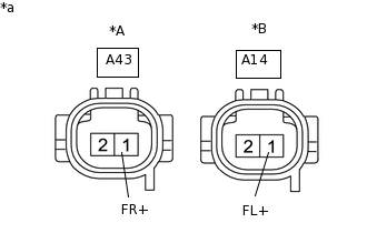
*A
for RH
*B
for LH
*a
Front view of wire harness connector
(to Front Speed Sensor)
Turn the power switch on (IG).
Measure the voltage according to the value(s) in the table below.
Standard Voltage
Table 3. for RH Tester Connection
Switch Condition
Specified Condition
A43-1 (FR+) - Body ground
Power switch on (IG)
5.7 to 14 V
Table 4. for LH Tester Connection
Switch Condition
Specified Condition
A14-1 (FL+) - Body ground
Power switch on (IG)
5.7 to 14 V
Result
Proceed to
OK
NG
RECONFIRM DTC
Turn the power switch off.
Reconnect the A14 or A43 front speed sensor connector.
Clear the DTCs.
Chassis > ABS/VSC/TRC > Clear DTCs
Turn the power switch on (READY).
Drive the vehicle at a speed of 20 km/h (12 mph) or more for at least 15 seconds.
Check if the same DTC is output.
Chassis > ABS/VSC/TRC > Trouble Codes
Result
Result
Proceed to
DTCs C1235/35 and/or C1236/36 are output.
A
DTCs C1235/35 and C1236/36 are not output.
B
REPLACE FRONT SPEED SENSOR
Turn the power switch off.
Replace the front speed sensor.
Result
Proceed to
NEXT
RECONFIRM DTC
Clear the DTCs.
Click here
Chassis > ABS/VSC/TRC > Clear DTCs
Turn the power switch on (READY).
Drive the vehicle at a speed of 20 km/h (12 mph) or more for at least 15 seconds.
Check if the same DTC is output.
Click here
Chassis > ABS/VSC/TRC > Trouble Codes
Result
Result
Proceed to
DTCs C1235/35 and/or C1236/36 are output.
A
DTCs C1235/35 and C1236/36 are not output.
B
B END
REPLACE FRONT AXLE HUB SUB-ASSEMBLY
Turn the power switch off.
Replace the front speed sensor rotor (front axle hub sub-assembly).
Tip:The front speed sensor rotor is incorporated into the front axle hub sub-assembly.
If the front speed sensor rotor needs to be replaced, replace the front axle hub sub-assembly.
Result
Proceed to
NEXT
RECONFIRM DTC
Clear the DTCs.
Click here
Chassis > ABS/VSC/TRC > Clear DTCs
Turn the power switch on (READY).
Drive the vehicle at a speed of 20 km/h (12 mph) or more for at least 15 seconds.
Check if the same DTC is output.
Click here
Chassis > ABS/VSC/TRC > Trouble Codes
Result
Result
Proceed to
DTCs C1235/35 and/or C1236/36 are output.
A
DTCs C1235/35 and C1236/36 are not output.
B
B END
CHECK REAR SPEED SENSOR AND SENSOR ROTOR
Remove the rear speed sensor and the component with the sensor rotor.
for Speed Sensor:Click here
for Speed Sensor Rotor:Click hereClick here
Check the speed sensor tip and speed sensor rotor.
OK
The sensor tip and rotor are free of scratches, oil, and foreign matter.
Note:If no damage to the speed sensor tip is found during this inspection, do not replace the speed sensor.
If there are any ferrous metal filings stuck to the rotor, this will result in a malfunction, so confirm that the rotor is not contaminated with foreign matter before replacing the sensor.
Check the speed sensor signal after cleaning or replacement.
Result
Proceed to
OK
NG
NG CLEAN OR REPLACE REAR SPEED SENSOR
CHECK HARNESS AND CONNECTOR (BRAKE BOOSTER WITH MASTER CYLINDER ASSEMBLY - REAR SPEED SENSOR)
Install the rear speed sensor and the component with the sensor rotor.
for Speed Sensor:Click here
for Speed Sensor Rotor:Click here
Make sure that there is no looseness at the locking part and the connecting part of the connectors.
Disconnect the A110 skid control ECU (brake booster with master cylinder assembly) connector.
Disconnect the M20 or N11 rear speed sensor connector.
Measure the resistance according to the value(s) in the table below.
Standard Resistance
Table 5. for RH Tester Connection
Condition
Specified Condition
A110-22 (RR+) - M20-1 (RR+)
Always
Below 1 Ω
A110-22 (RR+) or M20-1 (RR+) - Body ground
Always
10 kΩ or higher
A110-9 (RR-) - M20-2 (RR-)
Always
Below 1 Ω
A110-9 (RR-) or M20-2 (RR-) - Body ground
Always
10 kΩ or higher
Table 6. for LH Tester Connection
Condition
Specified Condition
A110-20 (RL+) - N11-1 (RL+)
Always
Below 1 Ω
A110-20 (RL+) or N11-1 (RL+) - Body ground
Always
10 kΩ or higher
A110-7 (RL-) - N11-2 (RL-)
Always
Below 1 Ω
A110-7 (RL-) or N11-2 (RL-) - Body ground
Always
10 kΩ or higher
Result
Proceed to
OK
NG
NG REPAIR OR REPLACE HARNESS OR CONNECTOR
INSPECT BRAKE BOOSTER WITH MASTER CYLINDER ASSEMBLY (SENSOR OUTPUT)
-
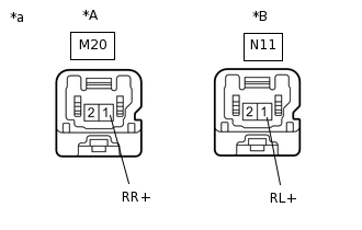
*A
for RH
*B
for LH
*a
Front view of wire harness connector
(to Rear Speed Sensor)
Reconnect the A110 skid control ECU (brake booster with master cylinder assembly) connector.
Turn the power switch on (IG).
Measure the voltage according to the value(s) in the table below.
Standard Voltage
Table 7. for RH Tester Connection
Switch Condition
Specified Condition
M20-1 (RR+) - Body ground
Power switch on (IG)
5.7 to 14 V
Table 8. for LH Tester Connection
Switch Condition
Specified Condition
N11-1 (RL+) - Body ground
Power switch on (IG)
5.7 to 14 V
Result
Proceed to
OK
NG
-
RECONFIRM DTC
Turn the power switch off.
Reconnect the N11 or M20 rear speed sensor connector.
Clear the DTCs.
Chassis > ABS/VSC/TRC > Clear DTCs
Turn the power switch on (READY).
Drive the vehicle at a speed of 20 km/h (12 mph) or more for at least 15 seconds.
Check if the same DTC is output.
Chassis > ABS/VSC/TRC > Trouble Codes
Result
Result
Proceed to
DTCs C1238/38 and/or C1239/39 are output.
A
DTCs C1238/38 and C1239/39 are not output.
B
REPLACE REAR SPEED SENSOR
Turn the power switch off.
Replace the rear speed sensor.
Click here
Result
Proceed to
NEXT
RECONFIRM DTC
Clear the DTCs.
Chassis > ABS/VSC/TRC > Clear DTCs
Turn the power switch on (READY).
Perform a road test.
Check if the same DTC is output.
Chassis > ABS/VSC/TRC > Trouble Codes
Result
Result
Proceed to
DTCs C1238/38 and/or C1239/39 are output.
A
DTCs C1238/38 and C1239/39 are not output.
B
Tip:If troubleshooting has been carried out according to Problem Symptoms Table, refer back to the table and proceed to the next step.
B END
REPLACE REAR AXLE HUB AND BEARING ASSEMBLY
Turn the power switch off.
Replace the rear speed sensor rotor (rear axle hub and bearing assembly).
Tip:The rear speed sensor rotor is incorporated into the rear axle hub and bearing assembly.
If the rear speed sensor rotor needs to be replaced, replace the rear axle hub and bearing assembly.
Result
Proceed to
NEXT
RECONFIRM DTC
Clear the DTCs.
Chassis > ABS/VSC/TRC > Clear DTCs
Turn the power switch on (READY).
Perform a road test.
Check if the same DTC is output.
Chassis > ABS/VSC/TRC > Trouble Codes
Result
Result
Proceed to
DTCs C1238/38 and/or C1239/39 are output.
A
DTCs C1238/38 and C1239/39 are not output.
B
Tip:If troubleshooting has been carried out according to Problem Symptoms Table, refer back to the table and proceed to the next step.
B END
INSPECT SKID CONTROL SENSOR WIRE
Turn the ignition switch off.
Make sure that there is no looseness at the locking part and the connecting part of the connectors.
for RH:
Disconnect the m1 and mM1 skid control sensor wire connectors.
for LH:
Disconnect the n1 and nN1 skid control sensor wire connectors.
-
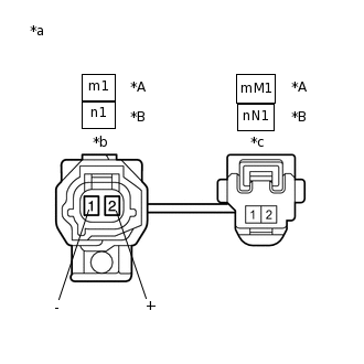
*A
for RH
*B
for LH
*a
Front view of Skid Control Sensor Wire
*b
Front view of wire harness connector
(to Sensor Side Connector)
*c
Front view of wire harness connector
(to Vehicle Side Connector)
Measure the resistance according to the value(s) in the table below.
Standard Resistance
for RH
Tester Connection
Condition
Specified Condition
m1-2 (+) - mM1-1
Always
Below 1 Ω
m1-1 (-) - mM1-2
Always
Below 1 Ω
m1-2 (+) - mM1-2
Always
10 kΩ or higher
m1-2 (+) or mM1-1 - Body ground
Always
10 kΩ or higher
m1-1 (-) - mM1-1
Always
10 kΩ or higher
m1-1(-) or mM1-2 - Body ground
Always
10 kΩ or higher
for LH
Tester Connection
Condition
Specified Condition
n1-2 (+) - nN1-1
Always
Below 1 Ω
n1-1 (-) - nN1-2
Always
Below 1 Ω
n1-2 (+) - nN1-2
Always
10 kΩ or higher
n1-2 (+) or nN1-1 - Body ground
Always
10 kΩ or higher
n1-1 (-) - nN1-1
Always
10 kΩ or higher
n1-1 (-) or nN1-2 - Body ground
Always
10 kΩ or higher
Result
Proceed to
OK
NG
CHECK HARNESS AND CONNECTOR (BRAKE BOOSTER WITH MASTER CYLINDER ASSEMBLY - REAR SPEED SENSOR)
Make sure that there is no looseness at the locking part and the connecting part of the connector.
Reconnect the mM1 or nN1 skid control sensor wire connector.
Disconnect the A110 skid control ECU (brake booster with master cylinder assembly) connector.
Measure the resistance according to the value(s) in the table below.
Standard Resistance
Table 9. for RH Tester Connection
Condition
Specified Condition
A110-22 (RR+) - m1-2 (+)
Always
Below 1 Ω
A110-22 (RR+) or m1-2 (+) - Body ground
Always
10 kΩ or higher
A110-9 (RR-) - m1-1 (-)
Always
Below 1 Ω
A110-9 (RR-) or m1-1 (-) - Body ground
Always
10 kΩ or higher
Table 10. for LH Tester Connection
Condition
Specified Condition
A110-20 (RL+) - n1-2 (+)
Always
Below 1 Ω
A110-20 (RL+) or n1-2 (+) - Body ground
Always
10 kΩ or higher
A110-7 (RL-) - n1-1 (-)
Always
Below 1 Ω
A110-7 (RL-) or n1-1 (-) - Body ground
Always
10 kΩ or higher
Result
Proceed to
OK
NG
NG REPAIR OR REPLACE HARNESS OR CONNECTOR
INSPECT BRAKE BOOSTER WITH MASTER CYLINDER ASSEMBLY (SENSOR OUTPUT)
-
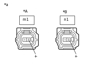
*A
for RH
*B
for LH
*a
Front view of wire harness connector
(to Rear Speed Sensor)
Reconnect the A110 skid control ECU (brake booster with master cylinder assembly) connector.
Turn the power switch on (IG).
Measure the voltage according to the value(s) in the table below.
Standard Voltage
Table 11. for RH Tester Connection
Condition
Specified Condition
m1-2 (+) - Body ground
Power switch on (IG)
5.7 to 14 V
Table 12. for LH Tester Connection
Condition
Specified Condition
n1-2 (+) - Body ground
Power switch on (IG)
5.7 to 14 V
Result
Proceed to
OK
NG
-
RECONFIRM DTC
Turn the power switch off.
Reconnect the m1 or n1 rear skid control sensor wire connector.
Clear the DTCs.
Chassis > ABS/VSC/TRC > Clear DTCs
Turn the power switch on (READY).
Drive the vehicle at a speed of 20 km/h (12 mph) or more for at least 15 seconds.
Check if the same DTC is output.
Chassis > ABS/VSC/TRC > Trouble Codes
Result
Result
Proceed to
DTCs C1238/38 and/or C1239/39 are output.
A
DTCs C1238/38 and C1239/39 are not output.
B
REPLACE REAR AXLE HUB AND BEARING ASSEMBLY
Turn the power switch off.
Replace the rear speed sensor rotor with rear speed sensor (rear axle hub and bearing assembly).
Tip:The rear speed sensor rotor is incorporated into the rear axle hub and bearing assembly.
If the rear speed sensor rotor needs to be replaced, replace the rear axle hub and bearing assembly with rear speed sensor.
Result
Proceed to
NEXT
RECONFIRM DTC
Clear the DTCs.
Chassis > ABS/VSC/TRC > Clear DTCs
Turn the power switch on (READY).
Drive the vehicle at a speed of 20 km/h (12 mph) or more for at least 15 seconds.
Check if the same DTC is output.
Chassis > ABS/VSC/TRC > Trouble Codes
Result
Result
Proceed to
DTCs C1238/38 and/or C1239/39 are output.
A
DTCs C1238/38 and C1239/39 are not output.
B
B END