SEAT BELT WARNING SYSTEM TERMINALS OF ECU
CHECK COMBINATION METER ASSEMBLY

Disconnect the G3 meter connector.
Measure the resistance and voltage according to the value(s) in the table below.
Terminal No. (Symbol)
Wiring Color
Terminal Description
Condition
Specified Condition
G3-1 (EP) - Body ground
W-B - Body ground
Ground
Always
Below 1 Ω
G3-25 (B) - Body ground
L - Body ground
Combination meter assembly B line
Always
11 to 14 V
G3-27 (IG+) - Body ground
R - Body ground
Combination meter assembly IG+ line
Engine switch on (IG)
11 to 14 V
G3-39 (CANL) - Body ground
W - Body ground
CAN communication line
Engine switch off
200 Ω or higher
G3-40 (CANH) - Body ground
LG - Body ground
CAN communication line
Engine switch off
200 Ω or higher
Reconnect the G3 meter connector.
Measure the voltage according to the value(s) in the table below.
Terminal No. (Symbol)
Wiring Color
Terminal Description
Condition
Specified Condition
G3-12 (P/SB) - Body ground
L - Body ground
Front passenger seat belt signal
Engine switch on (IG)
Front passenger seat occupied
Seat belt fastened
11 to 14 V
Engine switch on (IG)
Front passenger seat occupied
Seat belt unfastened
Alternating between 11 to 14 V and below 1 V
CHECK CENTER AIRBAG SENSOR ASSEMBLY
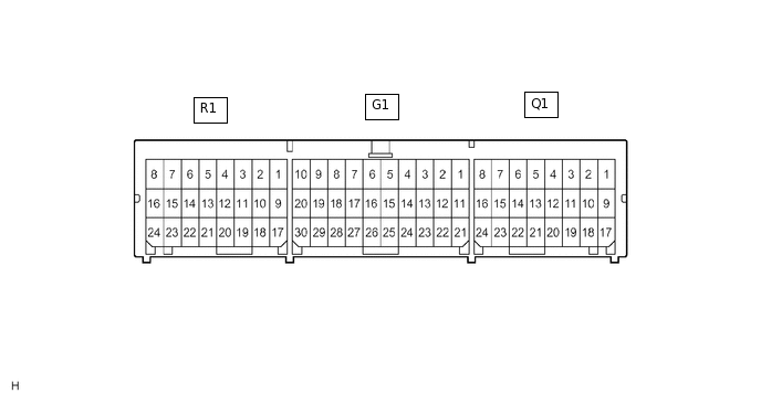
Terminal No.
Symbol
Description
R1-10
LBE+
Front seat inner belt assembly LH (Seat belt buckle switch LH)
R1-18
LBE-
Front seat inner belt assembly LH (Seat belt buckle switch LH)
G1-13
CANH
CAN communication line
G1-22
CANL
CAN communication line
-
*1
Main Body ECU (Multiplex Network Body ECU)
-
-
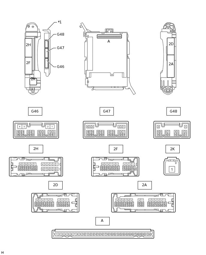
CHECK DRIVER SIDE JUNCTION BLOCK ASSEMBLY AND MAIN BODY ECU (MULTIPLEX NETWORK BODY ECU)
Remove the main body ECU from the driver side junction block assembly.
Measure the voltage and resistance according to the value(s) in the table below.
Terminal No. (Symbol)
Wiring Color
Terminal Description
Condition
Specified Condition
A-11 (GND1) - Body ground
None - Body ground
Ground
Always
Below 1 Ω
G46-3 (GND2) - Body ground
W-B - Body ground
Ground
Always
Below 1 Ω
A-30 (BECU) - Body ground
None - Body ground
Battery power supply (for CPU)
Always
11 to 14 V
A-31 (ALTB) - Body ground
None - Body ground
Battery power supply (for indicator)
Always
11 to 14 V
A-29 (ACC) - Body ground
None - Body ground
ACC power supply
Engine switch on (ACC)
11 to 14 V
A-32 (IG) - Body ground
None - Body ground
IG power supply
Engine switch on (IG)
11 to 14 V
Install the main body ECU to the driver side junction block assembly.
Measure the voltage according to the value(s) in the table below.
Terminal No. (Symbol)
Wiring Color
Terminal Description
Condition
Specified Condition
A-12 (PKB) - Body ground
None - Body ground
Parking brake switch signal
Engine switch on (IG), parking brake switch off
11 to 14 V
Engine switch on (IG), parking brake switch on
Below 1.5 V