CYLINDER HEAD REPLACEMENT
PROCEDURE
REPLACE INTAKE VALVE GUIDE BUSH
Heat the cylinder head sub-assembly to 80 to 100°C (176 to 212°F).
Place the cylinder head sub-assembly on wooden blocks.
-
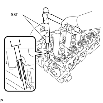
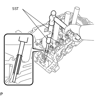
Using SST and a hammer, tap out the intake valve guide bush.
09201-10000
09201-01050
09950-70010
09951-07100
-
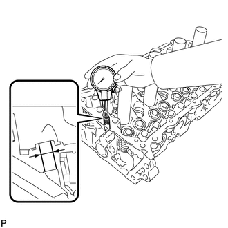
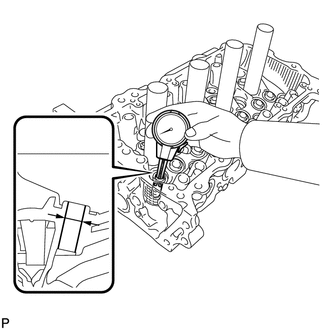
Using a caliper gauge, measure the intake valve guide bush bore diameter of the cylinder head sub-assembly.
Standard bush bore diameter
10.285 to 10.306 mm (0.40492 to 0.40575 in.)
New Guide Bush Selection Chart (STD or O/S 0.05)
Bush Size
Bush Bore Diameter
STD
10.285 to 10.306 mm (0.40492 to 0.40575 in.)
O/S 0.05
10.335 to 10.356 mm (0.40689 to 0.40772 in.)
If the intake valve guide bush bore diameter of the cylinder head sub-assembly is greater than 10.306 mm (0.40575 in.), machine the bush bore to the diameter of 10.335 to 10.356 mm (0.40689 to 0.40772 in.) to install an O/S 0.05 valve guide bush. If the intake valve guide bush bore diameter of the cylinder head sub-assembly is greater than 10.356 mm (0.40772 in.), replace the cylinder head sub-assembly.
Heat the cylinder head sub-assembly to 80 to 100°C (176 to 212°F).
Place the cylinder head sub-assembly on wooden blocks.
-
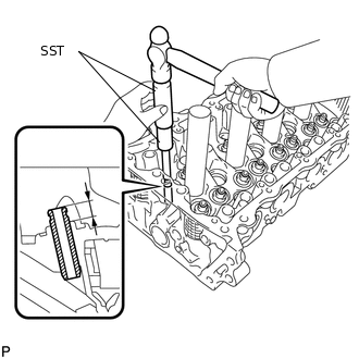
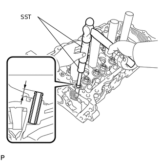
Using SST and a hammer, tap a new intake valve guide bush into the specified protrusion height.
09201-10000
09201-01050
09950-70010
09951-07100
Standard protrusion height
9.6 to 10.0 mm (0.378 to 0.394 in.)
-
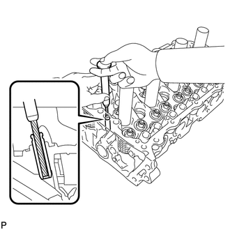
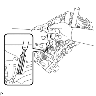
Using a sharp 5.5 mm reamer, ream the intake valve guide bush to obtain the standard oil clearance between the intake valve guide bush and intake valve stem.
Standard oil clearance
0.025 to 0.060 mm (0.000984 to 0.00236 in.)
REPLACE EXHAUST VALVE GUIDE BUSH
Heat the cylinder head sub-assembly to 80 to 100°C (176 to 212°F).
Place the cylinder head sub-assembly on wooden blocks.
-
Using SST and a hammer, tap out the exhaust valve guide bush.
09201-10000
09201-01050
09950-70010
09951-07100
-
Using a caliper gauge, measure the exhaust valve guide bush bore diameter of the cylinder head sub-assembly.
Standard bush bore diameter
10.285 to 10.306 mm (0.40492 to 0.40575 in.)
New Guide Bush Selection Chart (STD or O/S 0.05)
Bush Size
Bush Bore Diameter
STD
10.285 to 10.306 mm (0.40492 to 0.40575 in.)
O/S 0.05
10.335 to 10.356 mm (0.40689 to 0.40772 in.)
If the exhaust valve guide bush bore diameter of the cylinder head sub-assembly is greater than 10.306 mm (0.40575 in.), machine the bush bore to the diameter of 10.335 to 10.356 mm (0.40689 to 0.40772 in.) to install an O/S 0.05 valve guide bush. If the exhaust valve guide bush bore diameter of the cylinder head sub-assembly is greater than 10.356 mm (0.40772 in.), replace the cylinder head sub-assembly.
Heat the cylinder head sub-assembly to 80 to 100°C (176 to 212°F).
Place the cylinder head sub-assembly on wooden blocks.
-
Using SST and a hammer, tap a new exhaust valve guide bush into the specified protrusion height.
09201-10000
09201-01050
09950-70010
09951-07100
Standard protrusion height
9.6 to 10.0 mm (0.378 to 0.394 in.)
-
Using a sharp 5.5 mm reamer, ream the exhaust valve guide bush to obtain the standard oil clearance between the exhaust valve guide bush and exhaust valve stem.
Standard oil clearance
0.030 to 0.065 mm (0.00118 to 0.00256 in.)
REPLACE RING PIN
Note:It is not necessary to remove the ring pins unless they are being replaced.
Remove the 4 ring pins.
Using a plastic-faced hammer, tap in 4 new ring pins to the specified protrusion height.
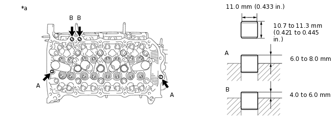
*a
Upper Side
-
-
Protrusion Height
Item
Protrusion Height
Ring pin A
6.0 to 8.0 mm (0.236 to 0.315 in.)
Ring pin B
4.0 to 6.0 mm (0.157 to 0.236 in.)
REPLACE STUD BOLT
Note:If any of the stud bolts is deformed or the threads are damaged, replace it.
Tip:There are 2 installation types for the No. 1 chain tensioner assembly.
Depending on the installation type, the number of stud bolts used will vary.
for No. 1 chain tensioner assembly installed with nut:
Remove the 13 stud bolts.
Using E5 and E8 "TORX" socket wrenches, install the 13 stud bolts.
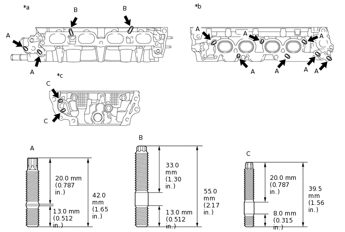
*a
Intake Side
*b
Exhaust Side
*c
Front Side
-
-
Stud bolt (A) and (B)
7.5 N*m
76 kgf*cm
66 in.*lbf
Stud bolt (C)
5.0 N*m
51 kgf*cm
44 in.*lbf
for No. 1 chain tensioner assembly installed with bolt:
Remove the 11 stud bolts.
Using an E8 "TORX" socket wrench, install the 11 stud bolts.
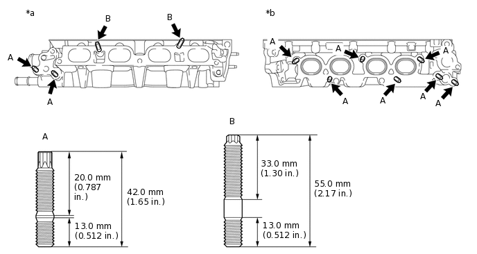
*a
Intake Side
*b
Exhaust Side
7.5 N*m
76 kgf*cm
66 in.*lbf