SFI SYSTEM ECM Back-up Power Source Circuit
DESCRIPTION
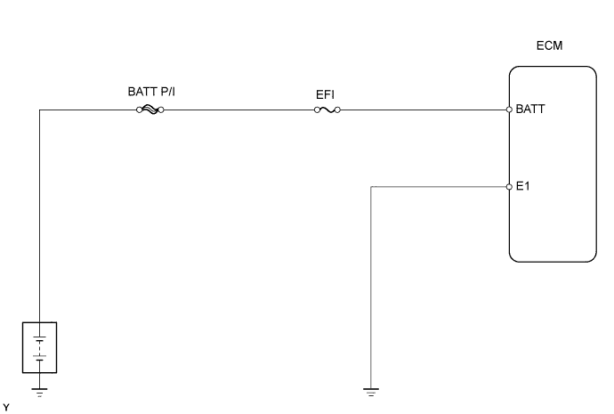
While the ignition switch is OFF, battery voltage is supplied to terminal BATT of the ECM for the DTC memory, air-fuel ratio adaptive control value memory, etc.
WIRING DIAGRAM
INSPECTION PROCEDURE
PROCEDURE
-
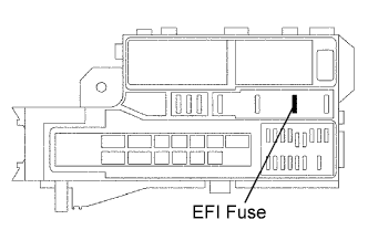
INSPECT FUSE (EFI)
-
Remove the EFI fuse from the engine room junction block.
-
Measure the resistance of the fuse.
Standard resistance Below 1 Ω
NG 
CHECK FOR SHORT IN ALL HARNESSES AND COMPONENTS CONNECTED TO FUSE
OK 
-
-
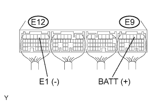
CHECK ECM (BATT VOLTAGE)
-
Turn the ignition switch ON.
-
Measure the voltage of the ECM connectors.
Standard voltage Tester Connection Specified Condition E9-3 (BATT) - E12-3 (E1) 8 to 14 V
OK
REPLACE ECM
NG
-
-
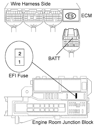
CHECK WIRE HARNESS (ECM - EFI FUSE, EFI FUSE - BATTERY)
-
Check the wire harness between the EFI fuse and ECM.
-
Remove the EFI fuse from the engine room junction block.
-
Disconnect the E9 ECM connector.
-
Measure the resistance of the wire harness side connectors.
Standard resistance Tester Connection Specified Condition J/B EFI fuse terminal 2 - E9-3 (BATT) Below 1 Ω J/B EFI fuse terminal 2 or E9-3 (BATT) - Body ground 10 kΩ or higher
-
-
Check the wire harness between the EFI fuse and battery.
-
Remove the EFI fuse from the engine room junction block.
-
Disconnect the positive (+) battery cable.
-
Measure the resistance of the wire harness side connectors.
Standard resistance Tester Connection Specified Condition Positive (+) battery cable - J/B EFI fuse terminal 1 Below 1 Ω Positive (+) battery cable or J/B EFI fuse terminal 1 -
Body ground
10 kΩ or higher
-
NG
REPAIR OR REPLACE HARNESS AND CONNECTOR
OK 
REPLACE ENGINE ROOM RELAY BLOCK
-