MANUAL TRANSMISSION UNIT REMOVAL
-
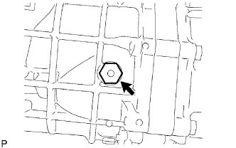
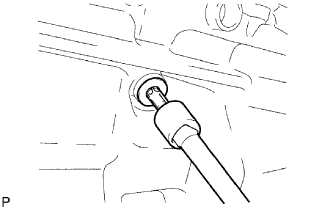
REMOVE FILLER PLUG
-
Remove the filler plug and gasket from the transmission case.
-
-
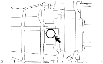
REMOVE DRAIN PLUG
-
Remove the drain plug and gasket from the transmission case.
-
-
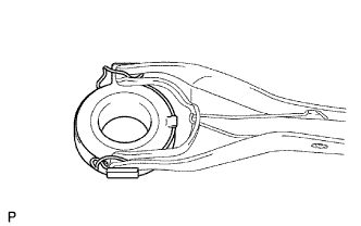
REMOVE CLUTCH RELEASE FORK
-
Remove the release fork and release bearing from the clutch housing.
-
-
REMOVE CLUTCH RELEASE BEARING ASSEMBLY
-
Remove the clip and release bearing from the release fork.
-
-
REMOVE RELEASE FORK SUPPORT
-
Remove the release fork support from the clutch housing.
-
-
REMOVE CLUTCH RELEASE FORK BOOT
-
Remove the clutch release fork boot from the clutch housing.
-
-
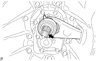
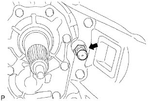
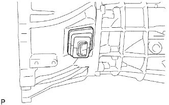
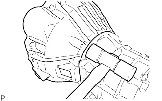
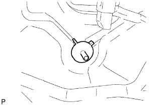
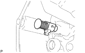
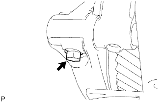
REMOVE BACK-UP LIGHT SWITCH ASSEMBLY
-
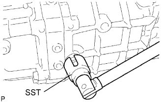
Using SST, remove the back-up light switch and gasket from the transmission case.
- SST
- 09817-16011
-
-
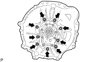
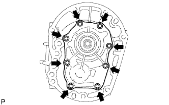
REMOVE CLUTCH HOUSING
-
Remove the 9 bolts.
-
Using a plastic-faced hammer, tap out the clutch housing from the transmission case.
-
-
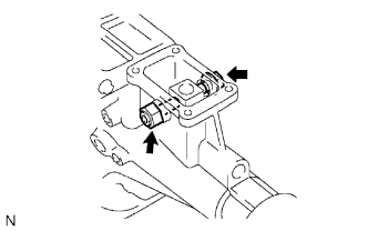
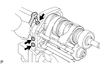
REMOVE RESTRICT PIN
-
Remove the 2 restrict pins from the extension housing.
-
-
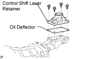
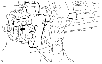
REMOVE CONTROL SHIFT LEVER RETAINER
-
Remove the 4 bolts from the extension housing.
-
Remove the shift lever retainer and oil deflector from the extension housing.
-
-
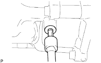
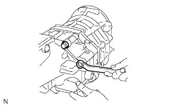
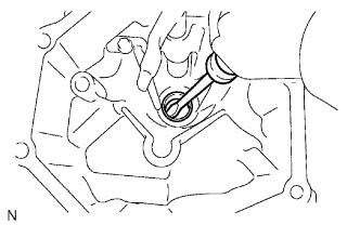
REMOVE SPEEDOMETER DRIVEN GEAR
-
Remove the bolt and driven gear.
-
-
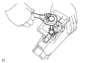
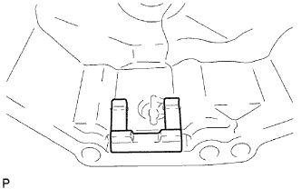
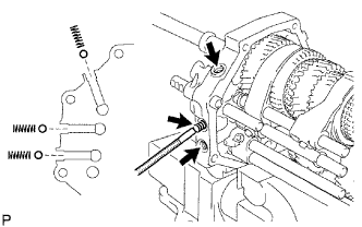
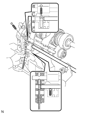
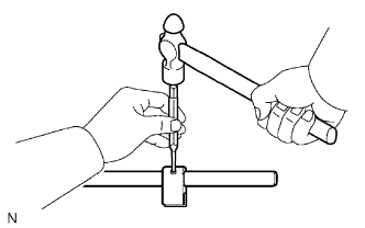
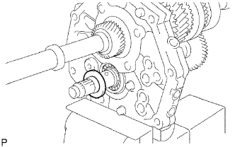
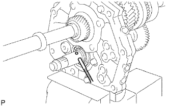
REMOVE SHIFT DETENT BALL
-
Using a T40 "torx" socket, remove the spring seat from the extension housing.
-
Using a magnetic finger, remove the compression spring and shift detent ball from the extension housing.
-
-
REMOVE EXTENSION HOUSING
-
Remove the bolt from the shift lever housing.
-
Remove the 8 bolts.
-
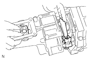
Using a plastic-faced hammer, tap the extension housing and remove the shift lever housing and the shift and select lever from the transmission case.
-
-
REMOVE TRANSMISSION MAGNET
-
Remove the magnet from the extension housing.
-
-
REMOVE OIL RECEIVER PIPE
-
Remove the receiver pipe from the extension housing.
-
-
REMOVE OIL RECEIVER
-
Remove the bolt and oil receiver.
-
-
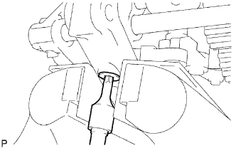
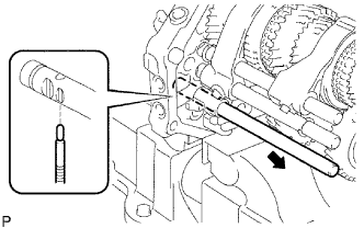
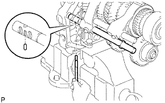
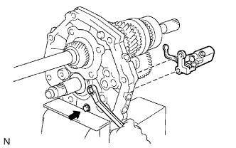
REMOVE REVERSE RESTRICT PIN
-
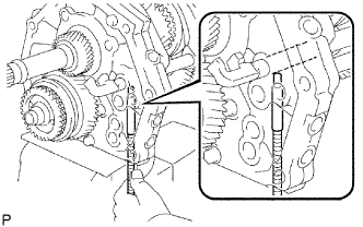
Using a T40 "torx" socket, remove the plug from the extension housing.
-
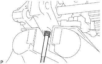
Using a 5 mm pin punch and hammer, tap out the restrict slotted spring pin from the extension housing.
-
Remove the restrict pin from the extension housing.
-
-
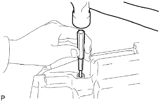
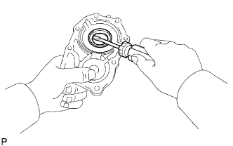
REMOVE EXTENSION HOUSING OIL SEAL
-
Using a screwdriver and hammer, tap out the oil seal from the extension housing.
-
-
REMOVE BEARING RETAINER FRONT
-
Remove the 8 bolts.
-
w/o Gasket:
Remove the bearing retainer from the transmission case.
-
w/ Gasket:
Remove the bearing retainer and gasket from the transmission case.
-
-
REMOVE TRANSMISSION FRONT BEARING RETAINER OIL SEAL
-
Using a screwdriver, pry out the oil seal from the bearing retainer front.
-
-
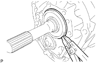
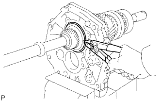
REMOVE FRONT BEARING SHAFT SNAP RING
-
Using a snap ring expander, remove the snap ring from the front bearing.
-
-
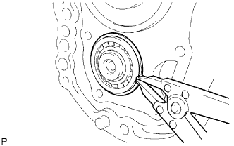
REMOVE NO. 1 COUNTER GEAR FRONT BEARING SNAP RING
-
Using a snap ring expander, remove the snap ring from the front bearing.
-
-
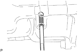
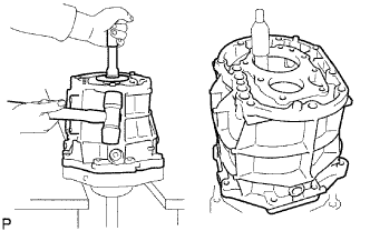
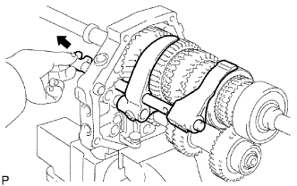
REMOVE MANUAL TRANSMISSION CASE
-
Stand the transmission as shown in the illustration.
-
Using a plastic-faced hammer, carefully tap off the transmission case.
-
Remove the transmission case from the intermediate plate as shown in the illustration.
-
-
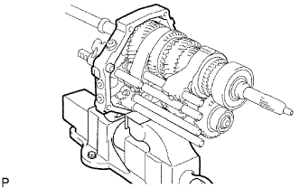
FIX INTERMEDIATE PLATE
-
Fix the intermediate plate in a vise.
-
-
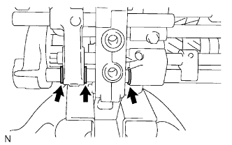
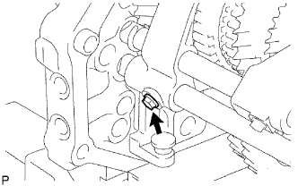
REMOVE SHIFT DETENT BALL
-
Using a T40 "torx" socket, remove the 3 spring seats from the intermediate plate.
-
Using a magnetic finger, remove the 3 compression springs and 3 shift detent balls from the intermediate plate.
-
-
REMOVE NO. 2 SHIFT DETENT BALL
-
Using a T40 "torx" socket, remove the spring seat from the intermediate plate.
-
Using a magnetic finger, remove the compression spring and detent ball from the intermediate plate.
-
-
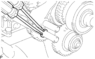
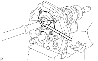
REMOVE NO. 4 SHIFT FORK SHAFT
-
Remove the bolt from the No. 3 gear shift fork.
-
Using 2 screwdrivers and a hammer, tap out the snap ring and 2 reverse shift head rings form the No. 4 shift fork shaft.
-
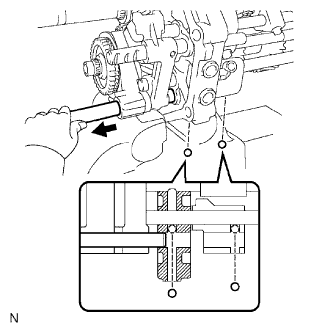
Remove the No. 4 shift fork shaft, ball pin shift interlocks and No. 3 gear shift fork from the intermediate plate.
-
-
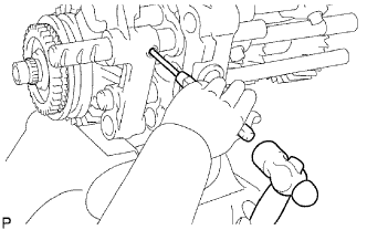
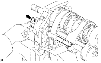
REMOVE NO. 5 SHIFT FORK SHAFT
-
Using a 5 mm pin punch and hammer, tap out the slotted spring pin from the reverse shift head.
-
Remove the reverse shift head and No. 5 shift fork shaft from the intermediate plate.
-
-
REMOVE NO. 3 SHIFT FORK SHAFT
-
Using a magnetic finger, remove the No. 2 shift interlock pin with the No. 3 shift fork shaft.
-
Remove the shift detent ball and compression spring from the reverse shift fork.
-
Using a magnetic finger, remove the No. 3 shift interlock pin from the intermediate plate.
-
-
REMOVE NO. 3 HEAD GEAR SHIFT
-
Using a 5 mm pin pinch and hammer, tap out the slotted spring pin from the No. 3 shift fork shaft.
-
Remove the No. 3 head gear shift from the No. 3 shift fork shaft.
-
-
REMOVE NO. 2 SHIFT INTERLOCK PIN
-
Using a magnetic finger, remove the No. 2 interlock pin from the No. 1 shift fork shaft.
-
-
REMOVE NO. 1 SHIFT FORK SHAFT
-
Using 2 screwdrivers and a hammer, tap out the snap ring from the No. 1 shift fork shaft.
-
Remove the bolt from the No. 1 gear shift fork.
-
Remove the No. 1 shift fork shaft from the intermediate plate.
-
-
REMOVE NO. 1 SHIFT INTERLOCK PIN
-
Using a magnetic finger, remove the No. 1 interlock pin from the intermediate plate.
-
-
REMOVE NO. 2 SHIFT FORK SHAFT
-
Remove the bolt from the No. 2 gear shift fork.
-
Using 2 screwdrivers and a hammer, tap out the snap ring from the No. 2 shift fork shaft.
-
Remove the No. 2 shift fork shaft, No. 1 gear shift fork and No. 2 gear shift fork from the intermediate plate.
-
-
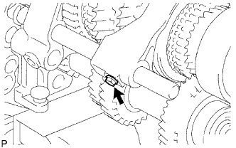
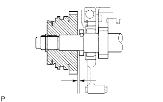
INSPECT COUNTER SHAFT 5TH GEAR THRUST CLEARANCE
-
Using a feeler gauge, measure the thrust clearance.
Standard clearance 0.125 to 0.325 mm (0.0049 to 0.0128 in.) Maximum clearance 0.325 mm (0.0128 in.)
-
-
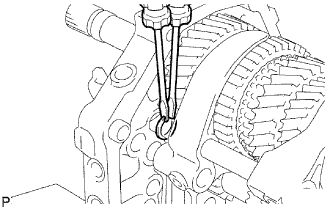
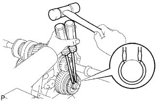
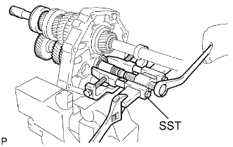
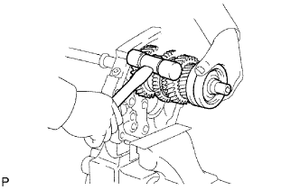
REMOVE COUNTER SHAFT 5TH GEAR ASSEMBLY
-
Using 2 screwdrivers and a hammer, tap out the snap ring from the counter gear.
-
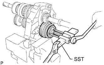
Using SST, remove the No. 5 gear spline piece and No. 3 synchronizer ring from the counter gear.
- SST
- 09950-50013 ( 09951-05010, 09952-05010, 09953-05010, 09954-05021 )
-
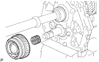
Remove the 5th gear and 5th gear bearing from the counter gear.
-
-
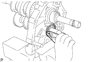
REMOVE 5TH GEAR THRUST WASHER
-
Remove the thrust washer from the counter gear.
-
Using a magnetic finger, remove the thrust washer lock ball from the counter gear.
-
-
REMOVE REVERSE SHIFT ARM BRACKET
-
Remove the 2 bolts and arm bracket with the shift arm from the intermediate plate.
-
-
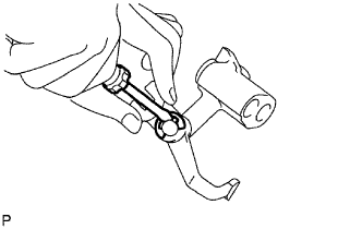
REMOVE REVERSE SHIFT ARM
-
Using a screwdriver, pry out the E-ring.
-
Remove the shift fork from the shift arm.
-
-
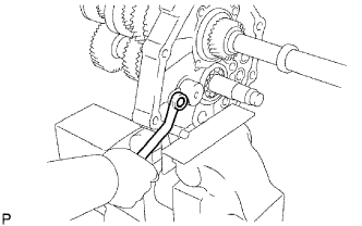
REMOVE REVERSE IDLER GEAR
-
Remove the bolt and idler gear shaft stopper from the intermediate plate.
-
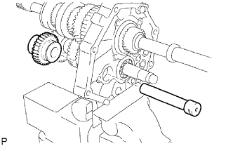
Remove the idler gear shaft and idler gear from the intermediate plate.
-
-
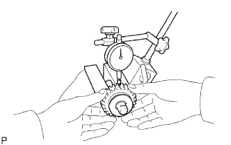
INSPECT REVERSE IDLER GEAR RADIAL CLEARANCE
-
Using a dial indicator, measure the radial clearance.
Standard clearance 0.04 to 0.08 mm (0.0016 to 0.0031 in.) Maximum clearance 0.08 mm (0.0031 in.)
-
If the clearance is greater than the maximum, replace the reverse idler gear.
-
-
-
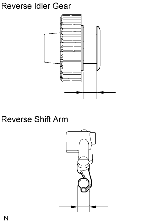
INSPECT REVERSE IDLER GEAR
-
Using a feeler gauge, measure the clearance between the reverse idler gear and reverse shift arm.
Standard clearance 0.05 to 0.35 mm (0.0020 to 0.0138 in.) Maximum clearance 0.35 mm (0.0138 in.)
-
If the clearance is greater than the maximum, replace the reverse idler gear and reverse shift arm.
-
-
-
REMOVE OUTPUT SHAFT REAR BEARING RETAINER
-
Using a T40 "torx" socket, remove the 4 screws and rear bearing retainer from the intermediate plate.
-
-
REMOVE COUNTER GEAR ASSEMBLY
-
Using a snap ring expander, remove the snap ring from the counter shaft center bearing.
-
Using SST, remove the center bearing, counter gear and input shaft from the intermediate plate.
- SST
- 09950-40011 ( 09951-04010, 09952-04010, 09953-04010, 09954-04010, 09955-04011, 09958-04011 )
-
-
REMOVE OUTPUT SHAFT ASSEMBLY
-
Using a snap ring expander, remove the snap ring from the output shaft center bearing.
-
Remove the output shaft from the intermediate plate by pulling on the output shaft and tapping on the intermediate plate with a plastic-faced hammer.
-