VEHICLE STABILITY CONTROL SYSTEM ABS Warning Light Remains ON
| DTC Code | DTC Name |
|---|---|
| ABS Warning Light Remains ON |
DESCRIPTION
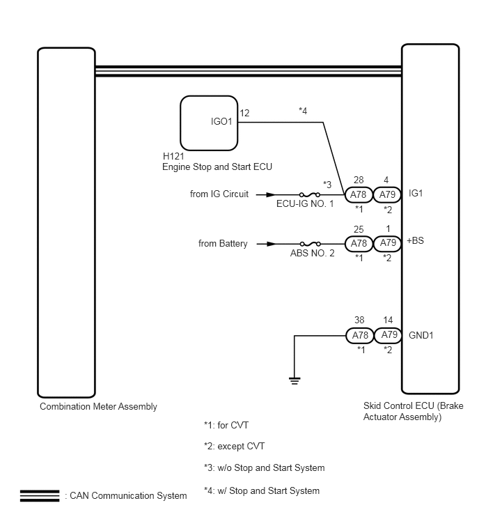
The skid control ECU (brake actuator assembly) is connected to the combination meter assembly via CAN communication.
If any of the following is detected, the ABS warning light remains on:
The skid control ECU (brake actuator assembly) connector is disconnected from the skid control ECU (brake actuator assembly).
There is a malfunction in the skid control ECU (brake actuator assembly) internal circuit.
There is an open in the harness between the combination meter and skid control ECU (brake actuator assembly).
The ABS and/or BA is defective.
In some cases, the GTS cannot be used when the skid control ECU (brake actuator assembly) is abnormal.
WIRING DIAGRAM
CAUTION / NOTICE / HINT
When replacing the skid control ECU (brake actuator assembly), perform system variant learning and acceleration sensor zero point calibration (Click here).
PROCEDURE
CHECK CAN COMMUNICATION SYSTEM
Check if a CAN communication system DTC is output (Click here).
Result
Result
Proceed to
DTCs are not output.
A
DTCs are output.
B
CHECK IF BRAKE ACTUATOR ASSEMBLY CONNECTOR IS SECURELY CONNECTED
Check if the skid control ECU (brake actuator assembly) connector is securely connected.
OK
The connector is securely connected.
CONNECT CONNECTOR TO BRAKE ACTUATOR ASSEMBLY CORRECTLY
CHECK BATTERY
CHECK TERMINAL VOLTAGE (POWER SOURCE TERMINAL)
REPAIR OR REPLACE HARNESS OR CONNECTOR (+BS CIRCUIT)
REPAIR OR REPLACE HARNESS OR CONNECTOR (IG1 CIRCUIT)
CHECK HARNESS AND CONNECTOR (GND1 TERMINAL)
REPAIR OR REPLACE HARNESS OR CONNECTOR (GND1 CIRCUIT)
READ VALUE USING GTS (ABS WARNING LIGHT)
Reconnect the A78 (for CVT) or A79 (except CVT) skid control ECU (brake actuator assembly) connector.
Connect the GTS to the DLC3.
Turn the ignition switch to ON.
Select the Data List on the GTS (Click here).
Table 1. ABS/VSC/TRC Tester Display
Measurement Item/Range
Normal Condition
Diagnostic Note
ABS Warning Light
ABS warning light/ ON or OFF
ON: Warning light on
OFF: Warning light off
-
Check the GTS display condition of the ABS warning light.
Result
Result
Proceed to
Display of the Data List remains ON.
A
Display of the Data List remains OFF.
B