AIR CONDITIONING SYSTEM(for Automatic Air Conditioning System) Ambient Temperature Sensor Circuit
| DTC Code | DTC Name |
|---|---|
| Ambient Temperature Sensor Circuit |
DESCRIPTION
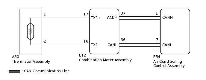
The thermistor assembly is installed in front of the cooler condenser assembly to detect the ambient temperature, which is used to control the air conditioning system. This sensor is connected to the combination meter assembly and detects fluctuations in the ambient temperature. This data is used for controlling the cabin temperature. The sensor sends a signal to the combination meter assembly. The resistance of the thermistor assembly changes in accordance with the ambient temperature. As the temperature decreases, the resistance increases. As the temperature increases, the resistance decreases.
The combination meter assembly applies a voltage (5 V) to the thermistor assembly and reads voltage changes due to changes in the resistance of the thermistor assembly.
WIRING DIAGRAM
PROCEDURE
INSPECT THERMISTOR ASSEMBLY
-
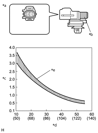
*a
Component without harness connected
(Thermistor Assembly)
*b
Sensing Portion
*c
Resistance (kΩ)
*d
Temperature (°C (°F))
*e
Allowable Range
Remove the thermistor assembly.
Measure the resistance according to the value(s) in the table below.
Standard Resistance
Tester Connection
Condition
Specified Condition
1 - 2
10°C (50°F)
3.00 to 3.73 kΩ
15°C (59°F)
2.45 to 2.88 kΩ
20°C (68°F)
1.95 to 2.30 kΩ
25°C (77°F)
1.60 to 1.80 kΩ
30°C (86°F)
1.28 to 1.47 kΩ
35°C (95°F)
1.00 to 1.22 kΩ
40°C (104°F)
0.80 to 1.00 kΩ
45°C (113°F)
0.65 to 0.85 kΩ
50°C (122°F)
0.50 to 0.70 kΩ
55°C (131°F)
0.44 to 0.60 kΩ
60°C (140°F)
0.36 to 0.50 kΩ
Note:Hold the sensor only by its connector. Touching the sensing portion may change the resistance value.
When measuring, the sensor temperature must be the same as the ambient temperature.
Tip:As the temperature increases, the resistance decreases (see the graph).
Result
Proceed to
OK
NG
-
CHECK HARNESS AND CONNECTOR (THERMISTOR ASSEMBLY - COMBINATION METER ASSEMBLY)
Disconnect the E12 combination meter assembly connector.
Measure the resistance according to the value(s) in the table below.
Standard Resistance
Tester Connection
Condition
Specified Condition
E12-17 (TX1+) - A50-1
Always
Below 1 Ω
E12-18 (TX1-) - A50-2
Always
Below 1 Ω
E12-17 (TX1+) - Body ground
Always
10 kΩ or higher
E12-18 (TX1-) - Body ground
Always
10 kΩ or higher
Result
Proceed to
OK
NG
NG REPAIR OR REPLACE HARNESS OR CONNECTOR
REPLACE COMBINATION METER ASSEMBLY
Replace the combination meter assembly.
Tip:Since the combination meter assembly cannot be inspected while it is removed from the vehicle, replace the combination meter assembly with a new or known good one and check that the condition returns to normal.
OK
Malfunction disappears.
Result
Proceed to
OK
NG
OK END (COMBINATION METER ASSEMBLY WAS DEFECTIVE)