MONITOR SYSTEM
-
FUNCTION OF MAIN COMPONENTS
-
The main components in the monitor system have the following functions:
Component Function Rear Television Camera Assembly Captures images of the area behind the vehicle and outputs video signals to the radio and display receiver assembly. Radio and Display Receiver Assembly Displays the image of the area behind the vehicle from the rear television camera assembly. Power Management Control ECU Sends a reverse signal to the No. 1 integration relay. No. 1 Integration Relay Sends the reverse signal from the power management control ECU to the radio and display receiver assembly.
-
-
OPERATING CONDITION
-
This system operates when all the conditions given below have been met:
Operating Condition
-
Power switch is on (Ready).
-
Reverse (R) has been selected.
-
-
-
FUNCTION
-
Area Displayed on screen
-
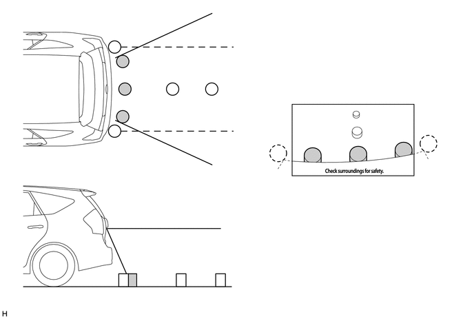
On the display, objects on the right of the vehicle appear on the right side of the display panel, and objects on the left of the vehicle appear on the left side of the display panel.
-
The television camera uses a wide-angle lens. The perceived distance from images that appear on the screen differs from the actual distance.
Note
The area displayed on the screen may vary according to vehicle status or road conditions. The area covered by the rear television camera assembly is limited. The rear television camera assembly does not show objects close to either corner of the bumper or show the area under the bumper.
-
-
Warning Message
-
A warning message appears at the bottom of the screen under the following conditions. The warning message appears in the same language that has been selected by the language selector of the multi-display.
Messages Appearing at Bottom of Screen Warning Message Outline Check surroundings for safety. This message always appears during system operation.
-
-
-
CONSTRUCTION
-
Rear Television Camera Assembly
-
The rear television camera assembly consists of a wide-angle lens and a Charge Coupled Device (CCD) camera.

Text in Illustration *1 Wide-angle Lens - -
-
-
Multi-display (Rear View Monitor Display)
-
In rear view monitor mode, the image of the area behind the vehicle captured by the rear television camera assembly is displayed on the radio and display receiver assembly.
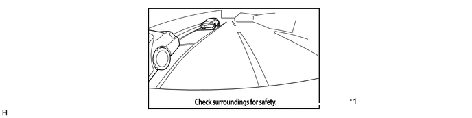
Item Description *1 Warning Message Display Area Area where warning messages are displayed.
-
-
-
FAIL-SAFE
-
The table below indicates malfunction detection items for the rear view monitor system.
Malfunctioning Parts Detection Item Function Rear Television Camera Assembly Transmission of rear television camera assembly malfunction signal Stops signal reception and displays a dark screen
-
-
DIAGNOSIS
-
The radio and display receiver assembly is equipped with a diagnosis function which can display a diagnosis menu for the rear view monitor system. For details, refer to the Repair Manual.
-