NAVIGATION SYSTEM Microphone Circuit between Microphone and Radio Receiver
| DTC Code | DTC Name |
|---|---|
| Microphone Circuit between Microphone and Radio Receiver |
DESCRIPTION
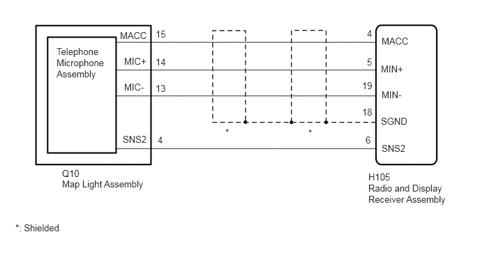
This circuit sends a microphone signal from the telephone microphone assembly to the radio and display receiver assembly.
It also supplies power from the radio and display receiver assembly to the telephone microphone assembly.
WIRING DIAGRAM
CAUTION / NOTICE / HINT
Check that the wire harness is properly installed and does not have any sharp bends, pinching or loose connections (Click here).
PROCEDURE
CHECK RADIO AND DISPLAY RECEIVER ASSEMBLY
-
Measure the resistance according to the value(s) in the table below.
Standard Resistance
Tester Connection
Condition
Specified Condition
H105-19 (MIN-) - Body ground
Always
Below 1 Ω
H105-18 (SGND) - Body ground
Always
Below 1 Ω
Measure the voltage according to the value(s) in the table below.
Standard Voltage
Tester Connection
Switch Condition
Specified Condition
H105-4 (MACC) - Body ground
Ignition switch ACC
4 to 6 V
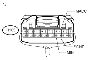
Table 1. Text in Illustration *a
Component with harness connected
(Radio and Display Receiver Assembly)
-
CHECK HARNESS AND CONNECTOR (RADIO AND DISPLAY RECEIVER ASSEMBLY - ROOF CONSOLE BOX ASSEMBLY)
Disconnect the H105 radio and display receiver assembly connector.
Disconnect the Q10 roof console box assembly connector.
Measure the resistance according to the value(s) in the table below.
Standard Resistance
Tester Connection
Condition
Specified Condition
H105-4 (MACC) - Q10-15 (MACC)
Always
Below 1 Ω
H105-5 (MIN+) - Q10-14 (MIC+)
Always
Below 1 Ω
H105-19 (MIN-) - Q10-13 (MIC-)
Always
Below 1 Ω
H105-6 (SNS2) - Q10-4 (SNS2)
Always
Below 1 Ω
H105-4 (MACC) - Body ground
Always
10 kΩ or higher
H105-5 (MIN+) - Body ground
Always
10 kΩ or higher
H105-19 (MIN-) - Body ground
Always
10 kΩ or higher
H105-18 (SGND) - Body ground
Always
10 kΩ or higher
H105-6 (SNS2) - Body ground
Always
10 kΩ or higher
REPAIR OR REPLACE HARNESS OR CONNECTOR
CHECK TELEPHONE MICROPHONE ASSEMBLY
Replace the telephone microphone assembly with a known good one (Click here).
Check if the same problem occurs again.
OK
Malfunction disappears.
END (TELEPHONE MICROPHONE ASSEMBLY IS DEFECTIVE)