LIGHTING SYSTEM
-
FUNCTION OF MAIN COMPONENTS
-
Daytime Running Light System
Component Function Main Body ECU (Network Gateway ECU) The main body ECU (network gateway ECU) receives various signals and illuminates the daytime running lights via the LED driver module. Headlight Dimmer Switch Assembly Light Control Switch The light control switch outputs a light control position signal and transmits it to the main body ECU (network gateway ECU). Turn Signal Switch*1 The turn signal switch outputs a turn signal control signal and transmits it to the main body ECU (network gateway ECU). Clock Assembly*1 Hazard Warning Signal Switch The hazard warning signal switch outputs the hazard warning signal switch on signal and transmits it to the main body ECU (network gateway ECU). Ignition Switch (Ignition or Starter Switch Assembly)*2 The ignition switch outputs the ignition switch status and transmits it to the main body ECU (network gateway ECU). Parking Brake Switch Assembly The parking brake switch assembly outputs the parking brake status (on/off) and transmits it to the main body ECU (network gateway ECU). ECM
-
The ECM outputs an engine speed signal and transmits it to the main body ECU (network gateway ECU).
-
The ECM outputs the shift position signal and transmits it to the main body ECU (network gateway ECU).*3
Transmission Control ECU Assembly*4 The transmission control ECU assembly outputs the shift position signal and transmits it to the main body ECU (network gateway ECU). DRL LH/RH Relay The DRL LH/RH relay supplies power to the LED driver modules. Headlight Assembly LH/RH LED Driver Module
-
Receives daytime running light control position signal and illuminates the daytime running lights.
-
Turns on or off or dims the daytime running lights in accordance with the condition of the turn signal lights or hazard warning lights.*1
Tech Tips
*1: Models for Korea
*2: Models without entry and start system
*3: Models with M/T
*4: Models with A/T
-
-
LED Headlight System
Component Function Main Body ECU (Network Gateway ECU)
-
The main body ECU (network gateway ECU) receives the light control switch position signal from the light control switch and transmits a signal to the H-LP relay.
-
The main body ECU (network gateway ECU) receives the high beam/low beam switch signal from the dimmer switch and transmits a signal to the DIM relay.
Headlight Dimmer Switch Assembly Light Control Switch The light control switch outputs a HEAD position signal and transmits it to the main body ECU (network gateway ECU). Dimmer Switch The Dimmer switch outputs a high beam/low beam switch signal and transmits it to the main body ECU (network gateway ECU). H-LP Relay The H-LP relay supplies power to the LED driver modules. DIM Relay The DIM relay transmits a HI/LO switch signal to the headlight assemblies. Headlight Assembly LH/RH LED (Light Emitting Diode) The Light Emitting Diode (LED) headlights shine ahead over a broader area and further forward, increasing the area visible to the driver. LED Driver Module
-
The LED driver module keeps a constant level of direct current applied to the LEDs, achieving stable LED illumination.
-
If a malfunction occurs in the LED headlight system, the LED driver module transmits a malfunction signal to the headlight leveling ECU.*
Headlight Leveling ECU Assembly* The headlight leveling ECU receives the LED headlight system malfunction signal from the LED driver module and transmits a signal to the combination meter assembly. Combination Meter Assembly* The LED headlight warning light illuminates to inform the driver when the headlight leveling ECU assembly detects malfunctions in this system. Tech Tips
*: Except Models for Korea
-
-
Automatic Headlight Beam Level Control System
Component Function Headlight Leveling ECU Assembly
-
The headlight leveling ECU assembly detects changes of vehicle movement based on the rear height control sensor sub-assembly LH and vehicle speed signal.
-
The headlight leveling ECU assembly outputs control signals to the headlight leveling motors based on the detected value.
-
This ECU provides initial set control and a fail-safe function.
Rear Height Control Sensor Sub-assembly LH The rear height control sensor sub-assembly LH detects vehicle movement and transmits a signal to the headlight leveling ECU assembly. Skid Control ECU The skid control ECU transmits a vehicle speed signal to the headlight leveling ECU assembly. Combination Meter Assembly Automatic Headlight Beam Level Indicator Light The automatic headlight beam level indicator light flashes to inform the driver when the headlight leveling ECU assembly detects malfunctions in this system. Headlight Assembly Headlight Leveling Motor
-
Based on the signals received from headlight leveling ECU assembly, each headlight leveling motor moves the projector unit in the headlight to vary its angle.
-
Each headlight leveling motor uses a stepper motor to precisely regulate the angle of the projector unit.
-
-
Automatic Light Control System
Component Function Main Body ECU (Network Gateway ECU) The main body ECU (network gateway ECU) receives various signals and illuminates the headlights, taillights, clearance lights, side marker lights*1 and license plate lights. Headlight Dimmer Switch Assembly Light Control Switch The light control switch transmits an AUTO position signal to the main body ECU (network gateway ECU). H-LP Relay The H-LP relay supplies power to the LED driver modules. DRL Relay*2 The DRL relay supplies power to the LED driver modules. TAIL Relay The TAIL relay supplies power to the side marker lights*1, taillight lights and license plate lights. Automatic Light Control Sensor The automatic light control sensor detects the ambient light level. Tech Tips
*1: Models for Korea
*2: Models with daytime running light system
-
Follow Me Home System (Models for Europe)
Component Function Main Body ECU (Network Gateway ECU) The main body ECU (network gateway ECU) receives a light control position signal and illuminates the low beam headlights via LED driver module. Headlight Dimmer Switch Assembly Light Control Switch The light control switch transmits a light control position signal to the main body ECU (network gateway ECU). H-LP Relay The H-LP relay shuts off power to the LED driver module. -
Light Auto Turn-off System
Component Function Main Body ECU (Network Gateway ECU) The main body ECU (network gateway ECU) receives various signals, and turns off the exterior lights. Headlight Dimmer Switch Assembly Light Control Switch The light control switch transmits a light control position signal to the main body ECU (network gateway ECU). H-LP Relay The H-LP relay shuts off power to the LED driver module. DRL LH/RH Relay*1 The DRL relay shuts off power to the LED driver module. TAIL Relay The TAIL relay shuts off power to the side marker lights*2, taillight lights and license plate lights. Ignition Switch (Ignition or Starter Switch Assembly)*3 The ignition switch outputs the ignition switch status and transmits it to the main body ECU (network gateway ECU). Front Door Courtesy Light Switch Assembly (Driver Side) Detects whether a door is open or closed and transmits a signal to the main body ECU (network gateway ECU). Tech Tips
*1: Models with Daytime Running Light System
*2: Models for Korea
*3: Models without entry and start system
-
Emergency Brake Signal (Except Models for Korea)
Component Function Brake Actuator Assembly Skid Control ECU Manages signals from each sensor and sends the operation signal of the emergency brake signal to the main body ECU (network gateway ECU). Speed Sensor Detects the wheel speed of each of the 4 wheels. Main Body ECU (Network Gateway ECU) Receives the emergency brake signal and controls the hazard warning lights. Stop Light Switch Assembly Detects the brake pedal depressing signal. Clock Assembly Hazard Warning Signal Switch Sends the operation signal of the hazard warning signal light to the main body ECU (network gateway ECU). Combination Meter Assembly Receives the emergency brake signal and blinks the turn signal indicator lights. Hazard Warning Light Blinks when a signal is received from the main body ECU (network gateway ECU).
-
-
OPERATING CONDITION
-
Daytime Running Light System
-
The daytime running lights illuminate when the following conditions are met:
-
Ignition switch is ON.
-
Engine is running.
-
The clearance lights are not on.*
-
The low beam headlights are not on.
-
The parking brake is off.
Tech Tips
*: Except Models for Korea
-
-
If a turn signal lights or hazard warning lights is flashing while the daytime running lights are on, the corresponding daytime running light is extinguished as shown below.*
-
If the right turn signal lights is flashing, the right daytime running light is extinguished.
-
If the left turn signal lights is flashing, the left daytime running light is extinguished.
-
If the hazard warning signal lights are flashing, both daytime running lights are extinguished.
Tech Tips
*: Models for Korea
-
-
-
Follow Me Home System
-
The follow me home system is enabled when the following conditions are met:
-
Ignition switch and ACC is OFF.
-
Light control switch OFF or AUTO position.
-
The headlight dimmer switch assembly is pulled to flash headlights once.
-
The key is removed from the ignition key cylinder.*
Tech Tips
*: Models without entry and start system
-
-
-
Light Auto Turn-off System
-
The exterior lights automatically turn off when all of the following conditions are met:
-
The ignition switch is turned (or ACC) from on to off.
-
The key is removed from the ignition key cylinder.*
Tech Tips
*: Models without entry and start system
-
-
-
Light Reminder System
-
The light reminder system will sound a buzzer if the following conditions are met:
-
The headlight dimmer switch assembly is in the head or tail position.
-
Ignition switch is OFF.
-
The key is removed from the ignition key cylinder.*
-
The driver door is opened.
Tech Tips
*: Models without entry and start system
-
-
-
Emergency Brake Signal (Except Models for Korea)
-
The activating and deactivating conditions for the emergency brake signal are as shown in the following table:
Condition Details Emergency Brake Signal Operating Conditions When all of the following conditions are met, the emergency brake signal starts operating:
-
Vehicle speed is above 55 km/h (35 mph).
-
Driver is depressing the brake pedal.
-
Emergency braking is detected from the vehicle deceleration.
Emergency Brake Signal Ending Conditions When any of the following conditions is met, the emergency brake signal stops operating:
-
Driver has released the brake pedal.
-
Emergency braking is no longer detected from the vehicle deceleration.
-
Driver has pressed the hazard warning signal switch.
-
-
-
-
FUNCTION
-
Automatic Headlight Beam Level Control System
-
The automatic headlight beam level control system mainly consists of the headlight leveling ECU assembly, rear height control sensor sub-assembly LH and 2 headlight leveling motors. The headlight leveling ECU assembly controls the system.
-
The ECU detects the movement of the suspension from the rear height control sensor sub-assembly LH and the vehicle speed from the skid control ECU.
-
The ECU then controls the headlight leveling motor based on this information, in order to change the projector unit angle.
-
When the engine is started, the headlight leveling ECU assembly drives the headlight leveling motor, moves the projector unit to the lower limit position and returns it to the proper position. The headlight leveling ECU assembly thus assesses the position of the headlight for reference control.
-
-
Follow Me Home System
-
The follow me home system is controlled by the main body ECU (network gateway ECU). The main body ECU (network gateway ECU) illuminates the low beam.
-
-
Light Reminder System
-
The light reminder system warns the driver using a buzzer when the main body ECU (network gateway ECU) detects a change in the driver's door courtesy light switch and sends a buzzer sound request signal to the combination meter assembly, if the ignition switch is turned off and the door is opened with the taillights kept on. The buzzer is located inside the combination meter assembly.
Light control switch position Ignition Switch (Ignition or Starter Switch Assembly) Door Buzzer Tail, Head switch off Open Sounds Closed -
-
-
-
CONSTRUCTION
-
LED Headlight System
-
Bi-function
-
When the low beam is selected, a shade blocks light from the high beam side.
-
When the high beam is selected, the headlight actuator slides the shade down, thus increasing the illumination area and improving visibility.
-
The bi-function is activated by the main body ECU (network gateway ECU). The main body ECU receives a signal to turn on the high beams from the headlight dimmer switch assembly, then activates the built-in headlight actuator to slide the shade down.
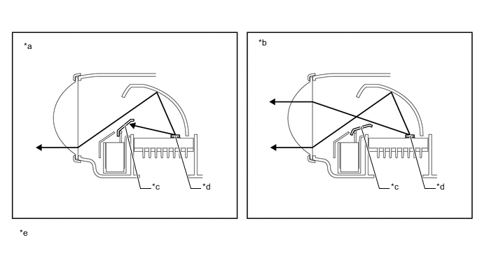
Text in Illustration (Bi-function: ) *a Low Beam *b High Beam *c Shade *d LED *e Illustration Provides Conceptual Image - -
-
-
LED Driver Module
-
When the light control switch is turned on, the LED driver modules immediately turn on the LEDs (approximately 0.1 seconds). In addition, by regulating the output current flowing into the LEDs at a specified level, the LED driver modules prevent the light from getting brighter and dimmer due to voltage variation.
-
If a malfunction occurs in the LED headlight system, the LED driver module transmits a malfunction signal to the headlight leveling ECU assembly. When the headlight leveling ECU assembly receives this malfunction signal, it transmits a signal to the combination meter assembly to warn the driver.*
Tech Tips
*: Except Models for Korea
-
-
-
-
FAIL-SAFE
-
LED Headlight System
-
If a malfunction occurs with the input voltage or output voltage of the LED driver module, the following fail-safe are implemented.
List of Fail-safe for the LED Driver Module Status Details During Input Voltage Malfunction Detection
-
Low Input Voltage
-
When the input voltage has dropped, the headlight stays on until a voltage of approx. 6 V (the light-on limit voltage). If the voltage drops approx. 6 V, the headlight switches off.
-
After the light switches off due to a drop of input voltage, headlight turns back on if the voltage reaches approx. 9 V or higher.
During Output Voltage Malfunction Detection
-
Output Open
-
Output Short
-
Short Between Output Terminals
-
If a malfunction is detected, the headlight switches off.
-
If the output voltage returns to normal after a malfunction is detected, the headlight switches back on.
-
-
-
Automatic Headlight Beam Level Control System
-
If the headlight leveling ECU assembly detects a malfunction in the automatic headlight beam level control system, it will take the actions indicated in the table below:
Trouble Item System Operation Automatic Headlight Level Indicator Light Ignition Power Over-Voltage Output of control signal to headlight leveling motor stops. Extinguished Ignition Power Under-Voltage Extinguished Rear Height Control Sensor Sub-assembly LH Power Over-Voltage Flashes Rear Height Control Sensor Sub-assembly LH Power Under-Voltage Flashes Rear Height Control Sensor Sub-assembly LH Signal Error Flashes Rear Height Control Sensor Sub-assembly LH Data Error During Initialization Flashes
-
-
-
DIAGNOSIS
-
Automatic Light Control System
-
When the main body ECU (network gateway ECU) detects malfunctions in the automatic light control system, Diagnostic Trouble Codes (DTCs) are stored in memory.
-
The DTCs can be read using the Grobal TechStream (GTS). For details, refer to the Repair Manual.
-
-