CLUTCH UNIT(for MA) INSTALLATION
PROCEDURE
INSTALL CLUTCH DISC ASSEMBLY
-
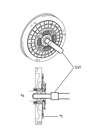
*1
Clutch Disc Assembly
*a
Flywheel Sub-assembly Side
Insert SST into the clutch disc assembly, then insert them both into the flywheel sub-assembly.
09301-00131
Note:Insert the clutch disc assembly in the correct direction.
-
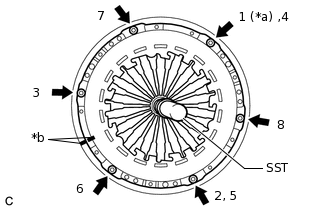
INSTALL CLUTCH COVER ASSEMBLY
-
*a
Temporarily Install
*b
Matchmark
Align the matchmark on the clutch cover assembly with that on the flywheel sub-assembly.
Following the procedure shown in the illustration, tighten the 6 bolts in order, starting with the bolt located near the knock pin at the top.
09301-00131
19.0 N*m
194 kgf*cm
14 ft.*lbf
Tip:Following the order shown in the illustration, tighten the bolts evenly one at a time.
Move SST up and down, right and left lightly after checking that the clutch disc assembly is in the center, and tighten the bolts.
-
INSTALL CLUTCH RELEASE FORK BOOT
Install the clutch release fork boot to the manual transaxle assembly.
INSTALL CLUTCH RELEASE FORK SUB-ASSEMBLY
-
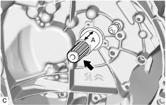

Clutch Spline Grease
Apply clutch spline grease to the input shaft splines.
Note:Do not apply grease to portion (A) shown in the illustration.
Grease
Toyota Genuine Clutch Spline Grease or equivalent
-
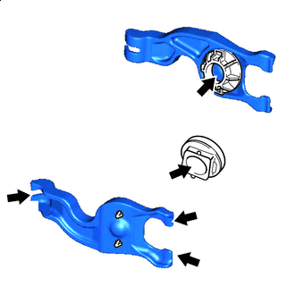
Release Hub Grease
Apply release hub grease to the contact surfaces of the clutch release fork sub-assembly and clutch release bearing assembly, and clutch release fork sub-assembly and release fork support.
Grease
Toyota Genuine Release Hub Grease or equivalent
Install the clutch release bearing assembly to the clutch release fork sub-assembly.
Install the clutch release fork sub-assembly with the clutch release bearing assembly to the manual transaxle assembly.
Note:After the installation, move the clutch release fork sub-assembly forward and backward to check that the release bearing slides smoothly.
-
INSTALL MANUAL TRANSAXLE ASSEMBLY